ADJUSTMENTS
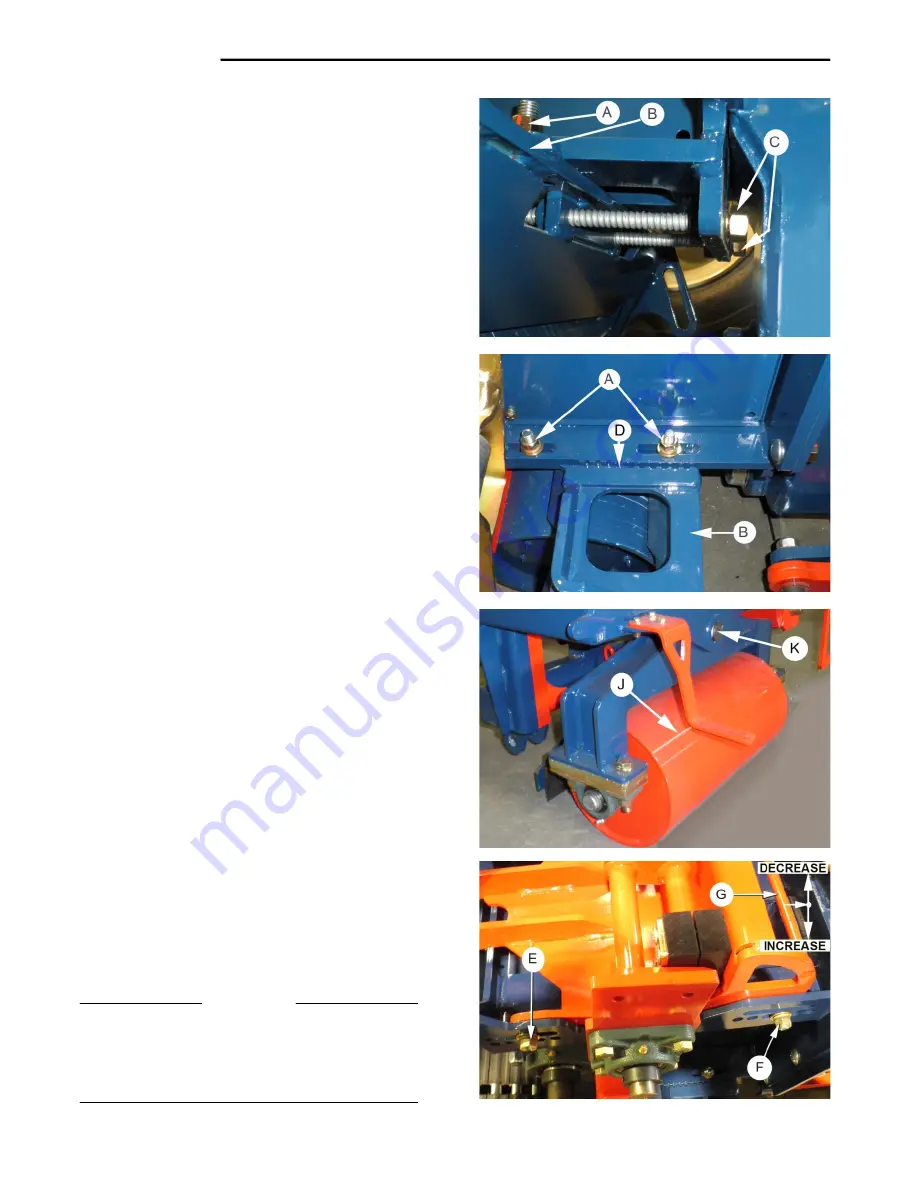
Ground Roller Adjustment.
To adjust the clearance between the Ground Roller and
the Cutting Blade :
•
Loosen the four Locknuts ‘
A
’, sufficient to allow
the Roller Bracket ‘
B
’, to ‘slide’ freely.
•
Turn the Adjusting Bolts ‘
C’,
‘
clockwise
’ to
reduce
the Roller to Blade clearance.
•
Turn the Adjusting Bolt ‘
C
’ ‘
counterclockwise
’ to
increase
the Roller to Blade clearance.
•
To ensure that the Roller Bracket is ‘square’ to
the Frame, turn the Adjusting Bolts ‘evenly’ on
both sides of the frame. Check that the ‘notches’
’
D
’, in the Roller Bracket and those in the Frame
are aligned equally, on both sides.
•
Fully tighten the Locknuts.
•
To prevent dirt build-up on the Roller, adjust the
Roller Scraper, to 1/32 in. clear of the Roller.
Pivoting Front Roller.
The Front Roller ‘
J
’ pivots in bearing ‘
K
’. The ‘polygon’
bearing does not require lubrication.
Lubricate the Roller Support Bearings. See page 6-12.
Depth of Cut.
During operation the Depth of Cut is controlled on the
Cab Control Handle. See Page 2-02.
Further adjustment can be made manually.
The machine is set-up at the factory with a Depth of Cut
setting for ‘average’ conditions.
If manual adjustment is required to the depth of cut :
•
Loosen the Rear Adjustment Bolts ‘
E
’.
•
Remove the Front Locator-bolts ‘
F
’.
•
To ‘
decrease
’ the Depth of Cut, lift the
Adjustment Frame ‘
G
’, ‘
UP
’, and fit the Front
Locator-bolts into the ‘
lower
’ hole in the
Adjustment Frame ‘
G
’.
•
To ‘
increase
’ the Depth of Cut, lower the
Adjustment Frame, and fit the Front Locator-bolts
into the ‘
upper
’ hole in the Adjustment Frame.
•
Remove the Rear Adjustment Bolts ‘
E
’, and fit
them into the same, ‘upper’ or ‘lower’, hole in the
Adjustment Frame ‘
G
’, as the front Locator Bolts.
IMPORTANT
Do not attempt
to install the front Locator-bolts in
the
lower set of holes
in the Cutter Head Frame and
the
top hole
in the Adjustment Frame, as the
Adjustment Frame will foul against the Cutter Head
Frame
6-10
Summary of Contents for 4000 R Series
Page 2: ......
Page 4: ......
Page 7: ......
Page 8: ......
Page 10: ......
Page 22: ...DECALS 1 12 ...
Page 23: ...DECALS 1 13 ...
Page 24: ...DECALS 1 14 ...
Page 25: ......
Page 26: ...1 16 ...
Page 28: ......
Page 30: ......
Page 34: ...This page left blank 2 04 ...
Page 36: ......
Page 38: ......
Page 42: ......
Page 57: ......
Page 58: ......
Page 59: ......
Page 60: ......
Page 61: ......
Page 62: ...This page left blank 3 22 ...
Page 63: ......
Page 64: ......
Page 67: ......
Page 68: ......
Page 73: ...HYDRAULIC SYSTEM Main Components Layout 4 05 ...
Page 74: ...HYDRAULIC SYSTEM ...
Page 75: ...HYDRAULIC SYSTEM Main Conveyor Hydraulic Layout 4 07 ...
Page 76: ......
Page 77: ......
Page 78: ......
Page 82: ......
Page 84: ......
Page 86: ......
Page 88: ......
Page 90: ......
Page 101: ...ELECTRICAL SYSTEM Inter Connect 5 13 ...
Page 102: ...ELECTRICAL SYSTEM Service Panel Under Cab Mount 5 14 ...
Page 103: ...ELECTRICAL SYSTEM Wiring Schematics 5 15 ...
Page 104: ...ELECTRICAL SYSTEM Wiring Schematics 5 16 ...
Page 105: ...ELECTRICAL SYSTEM Wiring Schematics 5 17 ...
Page 106: ...ELECTRICAL SYSTEM Wiring Schematics 5 18 ...
Page 107: ...ELECTRICAL SYSTEM Wiring Schematics 5 19 ...
Page 108: ......
Page 110: ......
Page 123: ...MAINTENANCE 6 13 ...
Page 126: ...LUBRICATION 6 16 ...
Page 127: ...LUBRICATION 6 17 ...
Page 128: ...LUBRICATION 6 18 ...
Page 130: ......
Page 132: ...AUTO STEER 7 02 ...
Page 133: ...AUTO STEER 7 7 03 ...
Page 136: ......
Page 139: ......
Page 140: ......
Page 141: ......
Page 142: ......
Page 143: ......
Page 144: ......
Page 145: ......
Page 146: ......
Page 147: ......
Page 148: ......
Page 149: ......
Page 150: ......
Page 151: ......
Page 152: ......
Page 153: ......
Page 154: ......
Page 155: ......
Page 156: ......
Page 157: ......
Page 158: ......
Page 159: ......
Page 160: ......
Page 161: ...ENGINE SECTION 9 Caterpillar Engine Operation and Maintenance ...


