MAINTENANCE
Main Conveyor Mat.
The Rubber Conveyor Mat has proven to work well in a
variety of conditions. It is the preferred choice of most
sod growers.
See page 6-03 for the installation of a new mat.
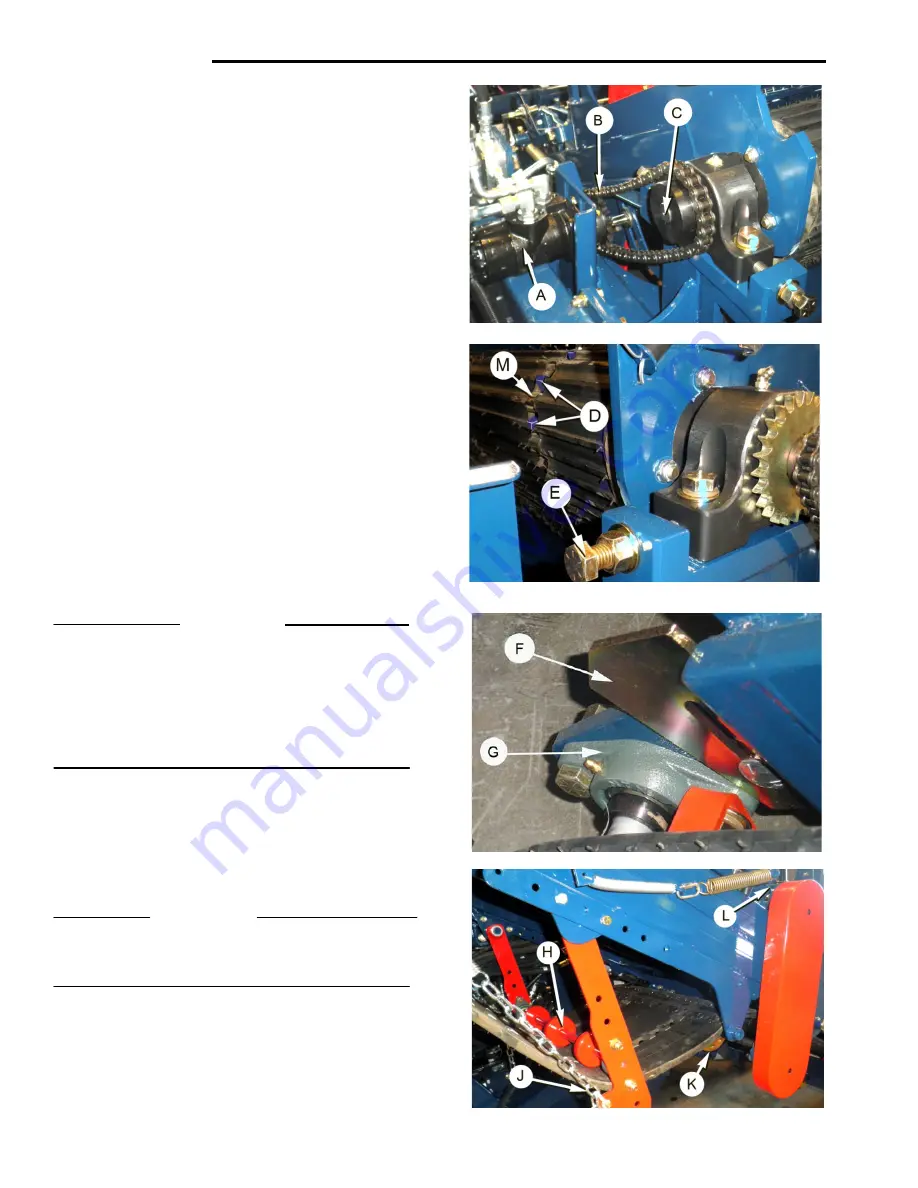
The Mat Drive is by Hydraulic Motor ‘
A
’ via Chain and
Sprockets ‘
B
’ to Conveyor Drive Shaft ‘
C
’.
The Mat Drive Sprockets ‘
D
’ run in slots in the mat.
The slots have replaceable Metal Clips ‘M’.
See page6-03 for Clip Replacement procedure.
To prevent premature/excessive wear the mat sprockets
must be ‘centered’ in the mat slots.
The ‘tracking ‘ of the mat square to the conveyor frame
is determined by the Crown Roller, see below.
The Mat Drive Shaft Alignment Bolts ‘
E
’, on both
sides of the conveyor frame, are set at the factory, and
should not require adjustment. (See page 6-04).
Crown Roller.
The Crown Roller, at the bottom end of the conveyor,
keeps the mat ‘tracking’ square on the conveyor.
The Roller Shaft is aligned in the frame with Taper
Wedges ‘
F
’,
located at each Roller Shaft Bearing ‘
G
’.
See the following pages for the correct alignment
procedure.
IMPORTANT
The Crown Roller must be set so that the sod guide
bracket does not hit against the conveyor mat.
Initially position the Roller shaft at the mid-point of
adjustment, determined by the backstroke of the cutter
blade and with allowance for the thickness of the mat.
Also allow for some forward movement of the assembly
during final alignment.
Mat Tension Idler.
Tension on the Conveyor mat is maintained by adjustable
Tension Idlers ‘H’.
Chains on the Idler Arms ‘
J
’ are attached to tension springs.
Move the chain links to adjust the tension.
IMPORTANT
Do not allow the idler arm to approach an angle of 90
degrees to the frame as it will be pulled over center and
mat tension will be lost.
Mat Support. 4 inch Roller Drive.
The Mid-Idler Shaft Sprockets Assembly supports
the mat.
The Sprockets ‘
K
’ drive the 4 inch Feed Roller ‘
L
’.
6-02
Summary of Contents for 4000 R Series
Page 2: ......
Page 4: ......
Page 7: ......
Page 8: ......
Page 10: ......
Page 22: ...DECALS 1 12 ...
Page 23: ...DECALS 1 13 ...
Page 24: ...DECALS 1 14 ...
Page 25: ......
Page 26: ...1 16 ...
Page 28: ......
Page 30: ......
Page 34: ...This page left blank 2 04 ...
Page 36: ......
Page 38: ......
Page 42: ......
Page 57: ......
Page 58: ......
Page 59: ......
Page 60: ......
Page 61: ......
Page 62: ...This page left blank 3 22 ...
Page 63: ......
Page 64: ......
Page 67: ......
Page 68: ......
Page 73: ...HYDRAULIC SYSTEM Main Components Layout 4 05 ...
Page 74: ...HYDRAULIC SYSTEM ...
Page 75: ...HYDRAULIC SYSTEM Main Conveyor Hydraulic Layout 4 07 ...
Page 76: ......
Page 77: ......
Page 78: ......
Page 82: ......
Page 84: ......
Page 86: ......
Page 88: ......
Page 90: ......
Page 101: ...ELECTRICAL SYSTEM Inter Connect 5 13 ...
Page 102: ...ELECTRICAL SYSTEM Service Panel Under Cab Mount 5 14 ...
Page 103: ...ELECTRICAL SYSTEM Wiring Schematics 5 15 ...
Page 104: ...ELECTRICAL SYSTEM Wiring Schematics 5 16 ...
Page 105: ...ELECTRICAL SYSTEM Wiring Schematics 5 17 ...
Page 106: ...ELECTRICAL SYSTEM Wiring Schematics 5 18 ...
Page 107: ...ELECTRICAL SYSTEM Wiring Schematics 5 19 ...
Page 108: ......
Page 110: ......
Page 123: ...MAINTENANCE 6 13 ...
Page 126: ...LUBRICATION 6 16 ...
Page 127: ...LUBRICATION 6 17 ...
Page 128: ...LUBRICATION 6 18 ...
Page 130: ......
Page 132: ...AUTO STEER 7 02 ...
Page 133: ...AUTO STEER 7 7 03 ...
Page 136: ......
Page 139: ......
Page 140: ......
Page 141: ......
Page 142: ......
Page 143: ......
Page 144: ......
Page 145: ......
Page 146: ......
Page 147: ......
Page 148: ......
Page 149: ......
Page 150: ......
Page 151: ......
Page 152: ......
Page 153: ......
Page 154: ......
Page 155: ......
Page 156: ......
Page 157: ......
Page 158: ......
Page 159: ......
Page 160: ......
Page 161: ...ENGINE SECTION 9 Caterpillar Engine Operation and Maintenance ...


