background image


B

B

R

R

O

O

U

U

W

W

E

E

R

R


4

4

0

0

0

0

0

0

-

-

R

R


S

S

e

e

l

l

f

f


P

P

r

r

o

o

p

p

e

e

l

l

l

l

e

e

d

d


S

S

o

o

d

d


H

H

a

a

r

r

v

v

e

e

s

s

t

t

e

e

r

r


O

O

p

p

e

e

r

r

a

a

t

t

o

o

r

r

s

s


M

M

a

a

n

n

u

u

a

a

l

l


          Kesmac Inc. 

          23324 Woodbine Avenue, Keswick Ontario Canada L4P 3E9 
          Tel (905) 476-6222 Fax (905) 476-6744  
          Web Site www.brouwerturf.com  Email [email protected] 


                                                                                                                                                            KM.99188 
                                                                                                                                                            April 2019 

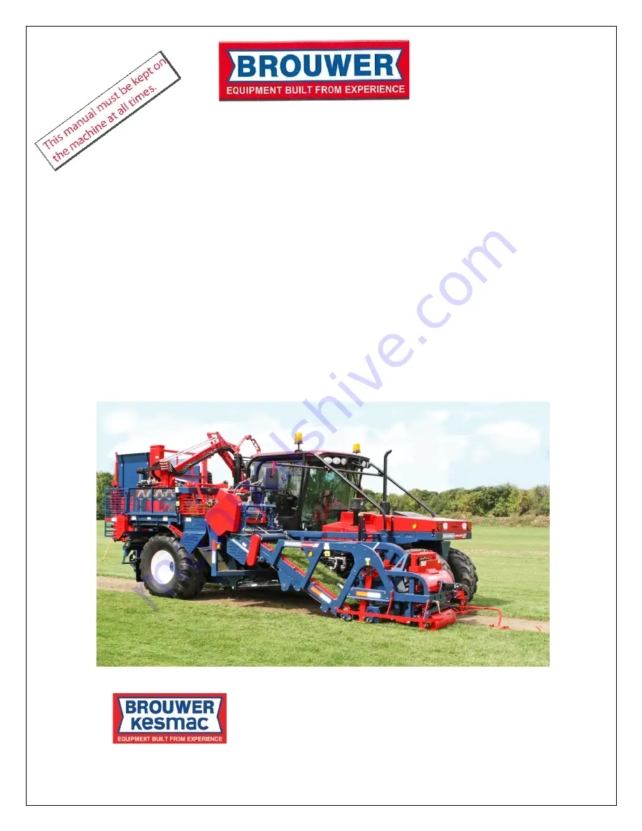
Summary of Contents for 4000 R Series

Page 1: ...el ll le ed d S So od d H Ha ar rv ve es st te er r O Op pe er ra at to or r s s M Ma an nu ua al l Kesmac Inc 23324 Woodbine Avenue Keswick Ontario Canada L4P 3E9 Tel 905 476 6222 Fax 905 476 6744 Web Site www brouwerturf com Email info kesmac com KM 99188 April 2019 ...

Page 2: ......

Page 3: ...i Specifications iii Caterpillar Service Center Locations iv Section 1 Safety Section 2 Cab Controls Section 3 Operation Section 4 Hydraulic System Section 5 Electrical System Section 6 Maintenance Schedule Lubrication Section 7 Electronic Auto Steer Section 8 Cab Maintenance Radio Owners Manual Section 9 Engine Operation and Maintenance Manual ...

Page 4: ......

Page 5: ...or understand them WARNING Brouwer Sod Harvesters are designed for safe efficient operation and must not be used for any purpose other than that for which they are designed Prior to being shipped from the manufacturer the machines are inspected to insure that all safety guards shields and warning safety operating decals are correctly positioned and secure Before operating the machine the operator ...

Page 6: ...A Roll Up Area B and Index Conveyor C These keys must be kept with the ignition key at all times Under no circumstance should the keys be left in the locks WARNING Do not operate the machine if any of the safety guards are damaged or missing In this manual for illustration purposes only some guards may not be shown ii ...

Page 7: ......

Page 8: ......

Page 9: ... Battery Isolator Switch 1 08 Fuel Filler Access Fuel Gauge 1 08 To move machine with no engine power Towing Transporting 1 09 Release Torque Hub Brake 1 09 Remove Conveyor 1 09 Cab Rear View Screen 1 10 Rear View Camera 1 10 Optional Camera Piling Cavity Area 1 10 Back Up Alarm 1 10 Service Maintenance Access Panels 1 11 Battery Location 1 11 Transport Tie Down Locations 1 11 Decals 1 12 13 14 15...

Page 10: ......

Page 11: ...chine until THE ENGINE IS SWITCHED OFF THE IGNITION KEY IS REMOVED THE CAB DOOR IS LOCKED Brouwer Turf Inc cannot stress too strongly the importance of Owners Operators adhering strictly to the safety recommendations as stated in this manual SAFETY WARNING For illustration purposes only some safety guards and shields may not be shown The machine must not be operated if any guards or shields are da...

Page 12: ... be thrown off the machine Also they may obstruct the ability of the operator or the operators view resulting in unsafe operation of the machine warning safety decals must be kept clean legible and undamaged Do not operate the machine if any decals are missing or damaged Obtain new decals from the factory 1 02 SAFETY Do not operate the machine if drugs alcohol or medication are being used that can...

Page 13: ...ured during transport SAFETY Operating Do not change the engine governor setting or over speed the engine WARNING Work in a ventilated area Never operate the machine without adequate engine exhaust ventilation Never run the engine in an enclosed area Exhaust fumes contain carbon monoxide and can be fatal if inhaled Inspect the area to harvested and remove any objects that may be hazardous or may c...

Page 14: ... recommended Tow bar failing The harvester becoming unstable and tipping The following procedures are recommended If possible reverse the machine out if it is mired in mud Dig mud out from behind the wheels Place boards behind under the wheels and reverse out slowly Keep bystanders clear of the rear of the machine 1 04 Dig mud out from in front of the wheels and drive ahead slowly Maintenance Safe...

Page 15: ...l gauge locations SAFETY Hydraulic System WARNING The Hydraulic System operates under high pressure To prevent serious injury from hot high pressure oil Never check for leaks with bare hands Use cardboard paper or wood High pressure oil can penetrate the skin If it is injected into the skin it must be surgically removed within a few hours by a doctor familiar with this type of injury Failure to do...

Page 16: ...to 30 minutes Get medical help immediately 1 06 If acid is swallowed Do not induce vomiting Drink large quantities of water or milk but do not exceed 2 liters 2 Quarts Get medical help immediately Battery Charging Charge batteries in an open well ventilated area away from sparks or open flame Unplug the charger before connecting or disconnecting the battery Jump Starting Check that the Jumper cabl...

Page 17: ...AFETY CAUTION Operating the machine with loose wheel lug nuts will result in damage to and require the replacement of wheel assembly components Always maintain the correct tire pressures Do not inflate tires above the recommended operating pressure shown on the side wall DANGER Never weld or heat a wheel tire assembly The heat can cause increased air pressure and result in the tire exploding Explo...

Page 18: ... area to be affected by heating If solvent or stripper is used wash them off with soapy water before doing any welding Remove any stripper or solvent containers and other flammable material from the area Allow a minimum of 15 minutes for fumes to disperse before welding Do not use chlorinated solvent in areas where welding will be done Do all work in an area that is well ventilated to allow fumes ...

Page 19: ...be resolved on site and is such that the engine has to be repaired at a Caterpillar Service Center it is recommended that the main conveyor is removed from the machine to enable easier transportation To remove the Main Conveyor Position a fork lift under the rear end of the conveyor frame or use slings to support it when it is disconnected from the main frame IMPORTANT To prevent loss of function ...

Page 20: ...NOTE If the camera is retro fitted in the field installation instructions included in the Kit are also shown on page 1 17 Interior Rear View Screen The operator must pay particular attention to the screen when reversing CAUTION To prevent possible personal injuries or damage The operator must be alert at all times to any persons or obstructions that may be in the vicinity of the machine Back Up Al...

Page 21: ...ured when raised with the safety supports provided A and B IMPORTANT To prevent overheating Check regularly particularly in dusty conditions that the radiator and coolers are free of dust or debris Battery Access To access the battery remove Panel Safe Transport Use the Tie Down Rings when transporting the machine Rear Tie Down Rings are located on the left and right side of the frame ahead of the...

Page 22: ...DECALS 1 12 ...

Page 23: ...DECALS 1 13 ...

Page 24: ...DECALS 1 14 ...

Page 25: ......

Page 26: ...1 16 ...

Page 27: ...g 2 Fig 3 Remove the lower rear panel and drill a 13 16in hole in the center of the panel Feed the camera cable through the panel into the cab Put silicone sealant on the cable grommet and fit it into the panel Refit the panel Fig 3 SAFETY Fig 4 Remove the two bolts C attaching the Cup holder Pull the Closing Panel D forward to remove it Remove Finishing Piece E held in place with Velcro Fig 4 Fig...

Page 28: ......

Page 29: ...d Brake and Reverse Lights Switches 2 01 Control Handle Euro Spec see P2 05 2 02 Console 8 Pad and Cab 20 Pad Controls Euro Spec see P2 05 2 02 Cab Controls 2 03 Road Lights Work lights Field Lights 2 03 A C Control 2 03 Rear View Screen 2 03 Washer Wiper 2 03 Radio Refer to Section 8 Owners Manual 2 03 Steering Pedestal Ignition Switch 2 03 Horn 2 03 Engine START Button 2 03 Turn Indicators 2 03 ...

Page 30: ......

Page 31: ...S 3 Conveyor Speed 4 Control Handle See page 2 02 5 Auto Steer Fine Adjust 1 Cab System Display Controller A Cab Console CAB CONTROLS 6 Cutter Speed 7 Engine RPM 8 8 Pad Control Panel See Page 2 02 9 20 Pad Control Panel See Page 2 02 10 Brake Clutch Inch Pedal 11 Switch Panel Switch Panel 20 Pad Control Outside E STOPS 2 01 ...

Page 32: ...ut Decrease 2 Depth of Cut Increase 3 Roll Size Decrease 4 Roll Size Increase 5 Auto Drive Speed Decrease 6 Auto Drive Speed Increase 7 Hold Release Pallet Unload 8 Auto Drive ON OFF Hold to Save Speed Console Control 8 Pad Cab Control 20 Pad 1 Arm Lift UP 11 Forks UP 2 Arm Lift DOWN 12 Forks DOWN 3 Arm Reach OUT 13 Injector UP 4 Arm Reach IN 14 Injector DOWN 5 Arm Slide BACK 15 Paddles UP 6 Arm S...

Page 33: ...w Screen 7 Cab O Head Light 8 Windshield Washer Wiper 9 Radio See Section 8 Owners Manual 10 Switch Panel See page 2 01 11 Ignition Switch 12 Horn 13 Turn Signals 14 Engine START 15 Brake Inch Clutch 16 Pedestal Adjust 17 Engine Diagnostic Display 18 Fuel Gauge Valid Data Display See Page 3 06 2 03 ...

Page 34: ...This page left blank 2 04 ...

Page 35: ...ab Control 20 Pad 1 Arm Lift UP 11 Forks UP 2 Arm Lift DOWN 12 Forks DOWN Stop Eject Conveyor Auto Mode 3 Arm Reach OUT 13 Injector UP 4 Arm Reach IN 14 Injector DOWN 5 Arm Slide BACK 15 Paddles UP 6 Arm Slide FORWARD 16 Paddles DOWN 7 Gripper Turn CW 17 Push Bar FORWARD 8 Gripper Turn CCW 18 Push Bar REV 9 EURO SPEC See below 19 EURO SPEC See below 10 EURO SPEC See below 20 Index Conveyor REV EUR...

Page 36: ......

Page 37: ... Start Up 3 08 Screen Navigation 3 08 Prepare machine to harvest 3 08 Machine Adjustments 3 09 Harvest Initializing 3 09 Harvesting Auto Mode System ON 3 10 Machine Adjustments 3 11 Harvesting Features 3 11 Auto Drive System 3 12 Operating Screens Main Operating Screen 3 12 13 Pallet Injector Screen 3 13 14 Arm Screen 3 14 15 Conveyors Screen 3 15 Cutter Screen 3 16 Propel Screen 3 16 Auto Steer S...

Page 38: ......

Page 39: ... and adjustment Starter Tray Bars E behind the Starter Gates F have Pins G that protrude 1 4 in below the Bar The pins grip the turf as it starts to roll up If the turf passes through but does not roll up tap the pins IN until they protrude 1 2 to 5 8 in The pins wear with use and must be adjusted or re placed as required In tender sod the pins may hold the underside of the sod too long causing a ...

Page 40: ... Conveyor Gripper Head and Pallet Injection area Failure to do so could result in serious injury or death Roll Position Sprockets IMPORTANT The Roll Position Sprockets are adjusted with the Lift Arms Adjuster to just hold the Roll They must not compress it The Roll Position Sprockets hold the sod roll as it is trans ferred to the Index Conveyor The sprockets automatically lift when a bad roll is e...

Page 41: ...The Controller also controls the multi grip single grip and squeeze functions of the Gripper Fingers E Cab Control Handle For operating functions e g Auto Steer Conveyor Flap Position Cutter Head etc See pages 3 10 11 Pallet Lift Forks There are two Proximity Sensors that sense the programmed positions of the Lift Forks Mast Mast HEIGHT Sensor F Mast BOTTOM Sensor G The Pallet Forks lower automati...

Page 42: ......

Page 43: ...D 2 Seat Switch 3 Machine Mode 4 Control Handle NEUTRAL 5 Auto Drive 6 Low Hyd Oil Level 7 FAULT 8 WARNING 9 Arm Lift Press ON 10 High Speed 11 Park Brake 12 High Hydraulic Oil Temp 13 E STOP Switch 14 Low Voltage 15 Pump P1 Charge Pressure Filter 16 Conveyor Down Pressure Status 17 Conveyor DOWN PROX Screen Buttons Typical for all screens 3 05 ...

Page 44: ...ngine has started Allow the hydraulic pumps to operate and circulate the oil in the system Use the Engine RPM Control to set engine speed See page 2 01 Fig 2 Switch the System Power ON Fig 2 Press Pad 2 to bring up Select Screen Fig 3 Scroll with Arrows A B to Select Warm Up Press Pad C OK to bring up Warm Up screen Press Button 1 to put machine in Ready mode Fig 4 Press Button B to run the Warm U...

Page 45: ...r Blade To reduce shock loads to the Cutter Motor when starting to harvest the Cutter Blade should be started before the Cutter Head is lowered to the ground Cutter Blade Speed Setting H Initially for best results start cutting at maximum speed and work back to the lowest speed that gives the best results Lower cutter speed results in less vibration The ground speed may have to be reduce when harv...

Page 46: ...d by pressing the Brake Clutch Inch Pedal without moving the Control Handle Releasing the foot pedal will return the machine to the control handle speed setting CAUTION Fully depressing the foot pedal will STOP the machine immediately If driving the machine prolonged distances or on rough terrain the Pallet Dispenser should be fully lowered and the Arm supported on the index conveyor with turf rol...

Page 47: ...Button 3 Scroll UP or DOWN using the UP DOWN arrows buttons to Position or Index Count and adjust to correct value or press Button 7 To Increase press right arrow button Decrease press left arrow button Harvest Initializing Aligning Machine to Cut Line Lower the Conveyor Pad A until the Conveyor DOWN Position Indicator on the display is ON keeping the Cutter Head off the ground Turn the Auto Steer...

Page 48: ... Index Conveyor one position Pulling the Trigger Switch DOWN will stop the Auto Mode The System is now OFF and the Cutter Head and Con veyor will stop The Arm will also stop regardless of its position so if poss ible turn the System OFF when the Arm is over the Index Conveyor machine counts stacked position when the Arm Returns HOME at its Home position NOTE Turning the System OFF will not stop th...

Page 49: ...e harvester and has to unload the pallets clear of the Harvest Cut line i e when reversing out When in this mode and the symbol is indicated ON solid Complete the Pallet Full Pallet Stop travel with System ON Auto Mode Machine will automatically STOP Reset the Control Handle to NEUTRAL to regain control Lift the Cutter Head Conveyor with Button B on Control Handle the Auto Steer will turn OFF auto...

Page 50: ...essed Control Console Operation and Harvesting Modes per Screen Harvest Main Screen Button 1 will send the machine main components to their Home Ready positions and enter its READY state Button 2 opens Select Screen Pop Up Menu to navigate to required screens Button 3 opens Stacking Items Pop Up Menu to adjust the following actions Empty Pallet Pressing and holding the OK Button will reset the pos...

Page 51: ...yor Range is 0 to 8 NOTE At eight Rolls in Auto Mode the Arm will pick up the rolls Button 6 on the Index Conveyor and stack them on the pallet Button 8 Enables the adjustment of the Cutter Head Roller Down Pressure Range 0 to 100 pressing and holding the Left Arrow Button decrease while at 0 will switch the Down Pressure Mode to FLOAT Pallet Injector Screen Button 1 will send the machines compone...

Page 52: ...cting a new pallet Tender Turf Mode ON or OFF ON When the Unload Ground Speed control is ON the Conveyor will slow down at the same percentage Injector Settings as the Unload Ground Speed is set at when unloading a full pallet OFF The Conveyor will not slow down when unload ing a full pallet Insert Fork Height Positions of Forks when injecting pallet Manually Not Harvesting See page 3 08 Pallet In...

Page 53: ...ast loaded into New Position Button 5 Enables the adjustment of the Maxi mum Arm Down Pressure Limit while stacking on the current pallet config uration Button 6 Opens the Single Grip Pop Up which allows the operator to select when the Arm picks up 4 or 5 rolls to be stacked on the current pallet configuration Button 7 Opens the Squeeze Pop Up which allows the operator to select which positions ar...

Page 54: ...N or OFF while the machine is Stopped Button 8 Enables the adjustment of the Auto Steer Left and Right Sensitivity Pressing Button 8 toggles between the Left and Right adjustments When highlighted adjustments are done with the Left and Right Arrows Buttons Adjusting these values with the Fine Adjust Control at the Neutral Position is recomm ended i Increased Higher numbers allow the Front Wheels t...

Page 55: ... Button 7 Opens the Strobe Light Menu which allows the operator to have the Strobe Lights ON or OFF during Harvest and Transport Modes Button 8 Enables the adjustment of Display Screen Brightness 0 to 100 Pressing and holding the Right Arrow Button will switch the Brightness Control to Auto Mode Warm Up Screen Button 1 Will send the machines components to their Home Ready positions and enter its R...

Page 56: ...ensor to act as a target Switch system power harvesting mode ON The GREEN LED should light up The YELLOW LED will light up when the Target is detected Remove the Target The YELLOW LED FIG 2 should not be ON If the LED remains ON carefully turn the Range Adjuster CCW until the LED does IMPORTANT not light up To ensure optimum performance the Sensors External Lens facing the target should be cleaned...

Page 57: ......

Page 58: ......

Page 59: ......

Page 60: ......

Page 61: ......

Page 62: ...This page left blank 3 22 ...

Page 63: ......

Page 64: ......

Page 65: ...llet Weight feature Note Control Console Will only weigh the pallet when HOLD is ON and the pallet is full The Main Screen will indicate that the Pallet HOLD Icon B is ON The weight of the Pallet will be shown at C on the Main Screen Main Screen The Pallet Injector Screen also shows the pallet weight at D Release the Pallet HOLD pad and continue to harvest the the pallets of sod until the total we...

Page 66: ...ight Indicator Option is installed it requires that Pressure Transducers are fitted as shown below The Pressure Transducers are wired to the Main Panel as shown Plug C30 In Main Panel Pressure Transducers on Mast Cylinder Lower Transducer Upper Transducer 3 26 ...

Page 67: ......

Page 68: ......

Page 69: ...el Sight Gauge a float will detect low oil level a warning will flash on the cab display and a buzzer will sound Stop operation immediately and investigate for oil leaks Refer to Section six page 6 13 for oil change schedule The Oil Cooler Fan engages automatically when the oil reaches a preset temperature sensed by a sending unit in the oil tank Oil temperature is shown on the Cab Display Control...

Page 70: ...Filter is mounted on the Drive System Pump P1 The Filter must be changed after the first 100 hours of oper ation IMPORTANT It is imperative that the area around the filter is cleaned before changing the filter to prevent any dirt from entering the drive system Controller A Filter Change Indicator After the initial filter change a warning symbol indicates that the filter pressure is at the point th...

Page 71: ...side To Drain the Oil Remove the bolts retaining the Plate A Reverse the Plate Rear Wheels with the top hat facing inwards and bolt it back into place This releases the Hub Brake allowing the wheel to be turned NOTE The oil should be drained after the machine has been driven and the oil in the hubs is warm Position the drain plug at the bottom Loosen the fill plug to relieve any vacuum Remove the ...

Page 72: ...n the operator s seat a second to attach the equip ment and adjust the pressure Loop Flushing Valve Located under the inner engine cover Fig 2 3 Remove the plug in the Valve and fit the Test Port Remove the Cap A Attach the Gauge B and Hose to the Test Port C Fig 2 Set the Engine rpm to 1800 With the machine stationary the gauge reading should be 350 375 psi Engage the Drive momentarily The indica...

Page 73: ...HYDRAULIC SYSTEM Main Components Layout 4 05 ...

Page 74: ...HYDRAULIC SYSTEM ...

Page 75: ...HYDRAULIC SYSTEM Main Conveyor Hydraulic Layout 4 07 ...

Page 76: ......

Page 77: ......

Page 78: ......

Page 79: ... ensure that all bystanders are well clear of the machine Decal Gripper Head manual controls The Gripper Head PVG Valves are located on the left side behind the cab Tank Top Return Connections A Medium Pressure Filter Arm Valve Hydraulic Oil Cooler Return B Front Bulkhead Filters Arm Filter Return C Case Drain Arm Pump D Case Drain Aux Pump E From Oil Cooler F Valve Drain Brake Release Motor Min G...

Page 80: ...d open the piling walls Check the tightness of each Bolt B to 200 lbs ft To ease access to the bottom two bolts use a suitable trolley jack to raise the machine CAUTION To prevent possible personal injury while tightening the lower bolts with the machine raised position a jack stand under the side beam as indicated Close the piling walls and re connect the cylinders NOTE The front wheels and torqu...

Page 81: ...8 9 are added to the Arm PVG Valve Bank The four hoses from the valves 8 9 are routed through the power trac unit A to bulkhead connections B C D E on the Arm Carriage From the bulkhead the hoses connect to the gripper head Refer to schematics sheets 1 and 2 Sheet 1 Gripper Head Hydraulic Diagram 4 13 ...

Page 82: ......

Page 83: ...the rear face of the oil tank as shown below The level indicator is located to the lower right of the filler cap A Flange Cap will be fitted at the previous location of the filler cap Check if this change has been made on this machine Page 4 01 in the manual will show the front location of the filler cap and oil level indicator 4 15 ...

Page 84: ......

Page 85: ...onnections 5 06 Multi Port Connector Blocks Locations 5 07 Proximity Sensors Locations 5 08 5 09 5 10 Drive Pump P1 Forward Reverse Solenoids 5 11 PVG Control Valves Plug Connections 6 7 8 Bank 5 11 Shipping Mode Disconnecting Conveyor Sensor Cables 5 12 Service Panel Cab Main Electrical Control Box Inter Connect 5 13 Electrical Schematics Service Panel Under Cab Mount 5 14 Control Console 5 15 Ov...

Page 86: ......

Page 87: ...a problem persists with the operation of the machine due to electrical faults it is recommended that you contact your Brouwer Dealer or the Factory Service Department The diagnosis and or repair of electrical problems that are beyond the scope of this manual must be done ONLY BY FACTORY TRAINED TECHNICIANS using the proper diagnostic equipment Battery Isolator Switch Glow Plug 50A Fuse Relay Box l...

Page 88: ......

Page 89: ...ions at the back of the main electrical control box These are identified as C28 C29 and C30 Plugs C28 and C29 are used and the functions are identified in the figure below Main Electrical Control Box Plug Pin Connections Refer to C28 and C29 to identify the plug pin connections Euro Plug Pin Connections C28 C29 5 02A ...

Page 90: ......

Page 91: ...ails Glow Plug Control Box See P5 01 for location Fuse Blocks 1 2 Service Panel Under Cab Fuse Block 1 Keep Alive Ign Sw 10A Reverse Lts Alarm10A Road Lts 15A Relays 13 Work Lts 2 Field Lts 15A Work Lts 2 15A Work Lts 1 10A 14 Field Lts Fuse Block 2 Power Port Ign 15A Wiper Radio 15A ECU Power 20A 15 Ignition Tail Alt Field 5A Signals 10A Starter 15A 16 Panel 17 HVAC Relays 3 Panel OFF 4 Reverse L...

Page 92: ...Plate Cab Display Controller A 20 Pad Control NOTE See pages 14 to19 for electrical schematics Control Console Control Handle Brake Inch Clutch Pedal Under Cab Service Panel See page 5 03 To Main Electrical Panel Page 5 02 System Power 5 04 ...

Page 93: ... check the wiring to the controller to restore power 2 Cab Display Loss of signal from the controller to the display If the above checks fail to restore functions call your Dealer or the factory Service Department Control Console Underside wiring 1 Control Handle 2 Auto Steer Fine Adjust Potentiometer 3 Cutter Speed Potentiometer 4 Conveyor Speed Potentiometer 5 E STOP Switch 6 8 Button Key Pad Co...

Page 94: ...e connection from the Multiport Blocks to the operating function IMPORTANT Do not direct jet of high pressure washer at electrical components Keep all electrical connections clean and tight NOTE ASV Anti Spin Valve PPU Pulse Pick up Press Pressure Pos Position Spare Not used RL Rear Left RR Rear Right FL Front Left FR Front Right 5 06 ...

Page 95: ...ctor Blocks NOTE Refer to page 5 02 for details of the Multi Ports cable connections at Main Electrical Control Box Arm Multiport Injector Multiport Left Rear Multiport Conveyor Multiport Front Three Multiports Rear Five Multiports 5 07 ...

Page 96: ...y Sensor or the target component is replaced it must be adjusted where applicable to allow a gap between the face of the sensor and the target as indicated below 1 Cut Off Sensor to Target 1 4 in to 3 8 in 2 Conveyor DOWN Sensor to Target 1 8 in to 1 4 in 3 Slab End Sensor See P3 18 for calibration 4 Roll Flap Tooth Count Sensor to Target 1 8 in max 5 Index Conv CLEATS position Sensor to Target 6 ...

Page 97: ...get 1 8in to1 4in 8 Pallet Disp Mid Sensor to Target 1 8in to 1 4in 9 Pallet Disp High Sensor to Target 1 8in to1 4in 10 11 Paddles Up Down Sensor to Target 1 8in to1 4in 12 Push Bar Away Sensor to Target 1 4in to 3 8in 13 Push Bar Home Sensor to Target 1 8in to1 4in 5 09 ...

Page 98: ...r removed No adjustment 16 Arm Rail Sensor No adjustment 17 Forks Bottom Sensor to Target 1 8in to 1 4in IMPORTANT Check regularly that there is no dirt or debris on the face of the sensors or between the sensors and their targets Do not direct high pressure water at any electrical components 5 10 ...

Page 99: ...oids 6 Bank PVG Control Valves 1 Oil Cooler Hyd Motor 2 Pallet Dispenser Cylinder 3 Paddles Lift Cylinder 4 Pallet Inject Motor 5 Wall Cylinders 6 Mast Cylinder 6 Bank PVG Valves 7 Bank PVG Valves 1 Arm Motor 2 Arm Lift Cylinder 3 Arm Reach Cylinder 4 Gripper Head Rotate Cylinder 5 Multi Grip Cylinder 6 Single Grip Cylinder 7 Squeeze Cylinder 7 Bank PVG Valves 8 Bank PVG Valves 1 Down Pressure Cyl...

Page 100: ...ressure Turn the Ignition ON Switch the System Power ON Go to System SELECT Screen PAD 2 Cab Display Controller A Select SET UP on Select Screen Select Screen Activate SHIPPING MODE PAD 6 Disconnect the sensor cables Switch the System Power OFF Turn the ignition OFF When the sensor cables are reconnected and the system is reactivated it will automatically return to the programmed settings Activate...

Page 101: ...ELECTRICAL SYSTEM Inter Connect 5 13 ...

Page 102: ...ELECTRICAL SYSTEM Service Panel Under Cab Mount 5 14 ...

Page 103: ...ELECTRICAL SYSTEM Wiring Schematics 5 15 ...

Page 104: ...ELECTRICAL SYSTEM Wiring Schematics 5 16 ...

Page 105: ...ELECTRICAL SYSTEM Wiring Schematics 5 17 ...

Page 106: ...ELECTRICAL SYSTEM Wiring Schematics 5 18 ...

Page 107: ...ELECTRICAL SYSTEM Wiring Schematics 5 19 ...

Page 108: ......

Page 109: ...ices 6 03 Conveyor Mat Metal Clips 6 03 Conveyor Mat Alignment 6 04 Index Conveyor Mat 6 05 Mat Sliders Replace 6 06 Mintex Metal Mats 6 07 Cut Off Length 6 08 Cut Off Blade 6 08 Cut Off Springs 6 08 Pitch Angle Adjust 6 09 Ground Roller to Cutter Blade Setting 6 09 Ground Roller Adjust 6 10 Depth of Cut Manual Adjust 6 10 Arm Drive Belt Replace Adjust Tension 6 11 LUBRICATION Recommended Lubricat...

Page 110: ......

Page 111: ... to the Cutter Blade Remove the Tie Bolt G and push the Side Arm forward to allow the Connecting Rod H to swing down Release the Bearing Lock Collar J and remove the Bearing Retaining Bolts K Slide the bearing OUT toward the Connecting Rod The self aligning bearings will allow the Eccentric Shaft to swing down sufficient to allow the belt to be removed from the Cutter Head Reverse the procedure to...

Page 112: ...the mat tracking square on the conveyor The Roller Shaft is aligned in the frame with Taper Wedges F located at each Roller Shaft Bearing G See the following pages for the correct alignment procedure IMPORTANT The Crown Roller must be set so that the sod guide bracket does not hit against the conveyor mat Initially position the Roller shaft at the mid point of adjustment determined by the backstro...

Page 113: ...n of the threaded stud Is broken off above the nut The special tools allow easy removal and installation of the splices KD90000 for use with hand tool KD89999 for use with air power When installing the new mat use expanding grips C to pull the mat ends together while securing them with zip ties until the splices have been fitted NOTE A Special Tool is available for mat installation as Shown Part N...

Page 114: ...he Crown Roller Tighten all fasteners Main Conveyor Tracking The Conveyor is maintained parallel to the Main Frame by the Conveyor Top Bearings M and also the Tracking Retainer Plate E in the Tracking Guide Assembly F bolted to the Bracket G on the main frame NOTE This is set up at the factory and should not need adjusting except if the Conveyor is removed for service or if damage occurs Conveyor ...

Page 115: ...l Cleats is determined by the position of the Sensor Flag G relative to the Sensor H IMPORTANT When adjusting the Sensor Flag start with it centered on the face of the Sensor then proceed to rotate it in small increments until the correct Roll Cleat position is obtained To adjust the Conveyor Cleats position NOTE CW CCW as viewed from arrow I Loosen the clamp bolt J in the Sensor Flag boss Rotate ...

Page 116: ... kit Pull the Mat clear of the top Drive Sprockets and off the bottom front Crown Roller Remove the Screws and Locknuts fastening the Sliders to the frame rails and pull the Sliders up and off the Rails It may be easier and quicker to cut badly worn Sliders off the Rails Clean up the rails for easier fitting of the new sliders Feed the Slider onto the rail from the top Knock it down the rail until...

Page 117: ...f the mat than the Drive Sprockets NOTE If the Sprocket Teeth show excessive wear it is recom mended that the Roll Up Frame Assembly be removed for complete overhaul To replace the Roll Up Mat A Loosen the Bearing Bolts E both sides Push the bearings forward to slacken the mat Locate the Removable Mat Connector D remove the two Jam Nuts F Pull the Connector out and remove the mat from the Frame In...

Page 118: ...stment The bungee Tensioner C attached to a hook on the Blade Holder positions the blade vertically but allows it to pivot forward when cutting Check that the edge of the Cut Off Blade Mount does not hit the sod on the down stroke as this will damage the sod and cause problems when the sod is laid NOTE A serrated blade is available for use in soft soil or exc essive thatch This blade will give a c...

Page 119: ...oosen the Lock bolts A in the Adjuster Bracket B Remove the Locator Bolts C To set the Pitch Angle for Hard Soil Pull the Adjuster Bracket FORWARD to increase the Cutter Blade Angle To set the Pitch Angle for soft Soil Push the Adjuster Bracket REARWARDS to decrease the Cutter Blade angle IMPORTANT The original Depth Adjustment Holes in the Adjuster Bracket must be used when replacing the Locator ...

Page 120: ... the Roller Support Bearings See page 6 12 Depth of Cut During operation the Depth of Cut is controlled on the Cab Control Handle See Page 2 02 Further adjustment can be made manually The machine is set up at the factory with a Depth of Cut setting for average conditions If manual adjustment is required to the depth of cut Loosen the Rear Adjustment Bolts E Remove the Front Locator bolts F To decr...

Page 121: ...elt off the drive motor and through the Arm Mount Rear Clamp Loosen the Socket Hd Bolts E Remove the Socket Hd Bolts F and slide the Belt sideways G out of the Clamp Install a new belt in the reverse order IMPORTANT To ensure that the drive belt is tensioned correctly the following procedure must be carried out It is important that the belt is not set too tight as this will result in premature bel...

Page 122: ...il to the Pallet Injector Shafts Linkages and Pivots Every 80 hours of operation Apply grease gun to all bearings Cut Off Cam Connecting Rods Cut Off Blade Shaft Ground Roller and Front Roller Crown Roller Main Conveyor Drive Shaft and Conveyor Sprocket Support Shaft Four Inch Roller Shaft Sprocket Drive Shaft and Pivot Arm Mat Idler Roller Shaft and Idler Arm Pivot Roll Up Mat Drive and Idler Sha...

Page 123: ...MAINTENANCE 6 13 ...

Page 124: ...system are shown below Depending on operating temperatures grease with base oils up to ISO VG1500 can be used to improve the lubricating film in slewing rings which are driven with very high loads and at very low speeds swiveling operation If these conditions occur contact INA Engineering Service Raceway Lubricant Manufacturer See following page for more important information on Slewing Ring lubri...

Page 125: ... of a large number of applications shows that guide values for the grease operating life can be taken as twice that of the guide value for the re lubrication interval At operating temperatures over 158deg F 70deg C both the re lubrication interval and the grease operating life are reduced In order to ensure operational safety the grease operating life should not exceed 3 years IMPORTANT When using...

Page 126: ...LUBRICATION 6 16 ...

Page 127: ...LUBRICATION 6 17 ...

Page 128: ...LUBRICATION 6 18 ...

Page 129: ...AUTO STEER SECTION 7 Auto Steer Set Up Set Up and Operation 7 01 Hydraulic Schematic 7 02 Electrical Schematic 7 03 Steer Cylinder replace set up 7 04 ...

Page 130: ......

Page 131: ...ual steering proceed to cut the starting strip The starting strip must be cut straight to ensure satisfactory operation of the Auto Steer When the starting strip has been cut Position the harvester parallel to the start strip with the Cutter Side Blade aligned with the cut edge of the turf Activate the Auto Steer to ON with Pad B on the Control Handle NOTE If the Guide Shoe lowers on the un cut tu...

Page 132: ...AUTO STEER 7 02 ...

Page 133: ...AUTO STEER 7 7 03 ...

Page 134: ... in the cylinder rod is aligned with the Cylinder Sensor C Turn the Rod End D to position the Lock bolt F 180 degrees opposite to the Cylinder Sensor C Tighten lock bolt F until it is hard against the flat portion of the Cylinder Rod B Tighten the Lock nut E Tighten the Locknut E This prevents the possible rotation of the cylinder rod if the lock nut E loosens causing misalignment of the sensors a...

Page 135: ...CAB MAINTENANCE SECTION 8 Controls 8 01 Air Conditioning Filter Service 8 01 Windshield Washer Fluid Container 8 01 Engine and Air conditioning Coolers 8 02 Radio Owners Manual ...

Page 136: ......

Page 137: ...Cab Air Conditioner Filter Remove the Air Cleaner Cover to access the Filter Unscrew the retainer nut and remove the filter Thoroughly clean the filter or fit a new one if needed When fitting the cover ensure that the rubber seal is intact and correctly seated Windshield Washer The Washer Fluid Container is located as shown Always use a quality washer fluid that is suitable for the temperature zon...

Page 138: ...rcooler and Air Conditioner Coolers Check regularly and remove any dust or debris from the coolers that will affect their efficiency See section 9 Engine Operation and Service Manual for Radiator Cooler maintenance procedure 8 02 ...

Page 139: ......

Page 140: ......

Page 141: ......

Page 142: ......

Page 143: ......

Page 144: ......

Page 145: ......

Page 146: ......

Page 147: ......

Page 148: ......

Page 149: ......

Page 150: ......

Page 151: ......

Page 152: ......

Page 153: ......

Page 154: ......

Page 155: ......

Page 156: ......

Page 157: ......

Page 158: ......

Page 159: ......

Page 160: ......

Page 161: ...ENGINE SECTION 9 Caterpillar Engine Operation and Maintenance ...

Reviews: