- 37 -
10.
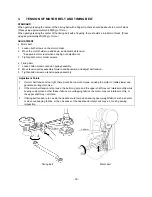
PRESSER BAR HEIGHT
STANDARD
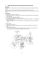
If presser bar is set to appropriate height and presser foot lifter is raised (up one step), the distance between top
surface of needle plate and bottom of presser bar should be between 6.0-6.5mm.
ADJUSTMENT
1.
Remove BH switch base board.
2.
Raise presser foot lifter up one step.
3.
Loosen presser bar guide bracket screw.
4.
Raise and lower presser bar, and adjust so that height is within 6.0-6.5mm.
5.
Fasten presser bar guide bracket screw.
6.
Attach BH switch base board.
Adjustment Points
* Check to make sure that side of presser foot is parallel with feed dog grooves of needle plate.
(1) Use the J sewing foot.
(2) If the presser bar is not parallel with feed dog grooves, the needle may come into contact with the presser
foot or the fabric may not feed correctly when overcasting presser foot.
6-6.5mm
4
3
5
2
6
1
Summary of Contents for PE-300S
Page 1: ... 2 1999 ...
Page 4: ... 2 1 MECHANICAL CHART EMBROIDERY UNIT MECHANISM ...
Page 6: ... 4 3 ELECTRONIC PARTS ARRANGEMENT CHART ...
Page 7: ... 5 4 CONTROL SYSTEM BLOCK DIAGRAM ...
Page 11: ... 9 9 1 1 9 9 8 7 7 3 3 6 6 2 2 3 1 1 9 5 5 5 ...
Page 13: ... 11 12 11 17 20 20 15 16 19 20 18 13 14 10 10 ...
Page 15: ... 13 25 2 25 1 23 36 29 29 37 32 22 22 24 24 27 27 30 30 31 31 33 33 34 32 28 36 35 26 ...
Page 17: ... 15 39 39 38 ...
Page 19: ... 17 Diagram A 45 1 45 2 42 53 48 52 49 50 43 42 41 44 47 47 46 40 51 ...
Page 21: ... 19 Diagram A 55 60 56 54 58 64 64 65 61 61 59 59 54 57 ...
Page 23: ... 21 diagram A 74 69 69 68 69 75 73 72 70 67 67 ...
Page 25: ... 23 77 78 84 68 84 78 78 79 86 86 84 ...
Page 27: ... 25 5 3 2 2 2 2 3 4 1 5 ...
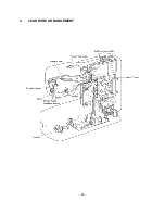
Page 28: ... 26 3 LEAD WIRE ARRANGEMENT ...
Page 57: ...PE 300S H8080132 ...


