- 38 -
11.
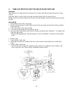
BUTTON HOLER (POSITION OF BUTTONHOLE LEVER)
STANDARD
When the BH (buttonhole) lever is lowered, the clearance of the front part of the buttonholer foot (A) should be
1.5mm, and when the presser foot lifter is lowered, BH0 should touch BH1.
ADJUSTMENT
1.
Flip on power switch, select button holing stitch (bar tack).
2.
Attach Buttonholer foot (A), set clearance at front of foot to 1.5mm and lower presser foot lifter.
3.
Turn BH eccentric shaft, adjust position of BH switch lever so that BH10 touches BH1.
4.
To check length of finished buttonholes, set a 20mm round button in the buttonholer foot and sew a bar tack
stitch.
5.
Check to make sure that inside of vertical bar tacking is between 20-30mm.
Adjustment Points
* Pull buttonholer foot all the way out, and check switch operation when you sew where two notches of
buttonholer foot are returned.
(1) to set clearance at front of buttonholer foot (A) to 1.5mm, set a 1.5mm coin into front section.
(2) Turning BH eccentric shaft clockwise will widen the clearance between BH0 and BH1.
(3) If length of buttonhole is too short, bend BH1 so that BH2 moves further away from BH0. If too long, bend
BH2 so that it comes nearer to BH0.
Switch
monitoring
BH2
BH1
1.5mm
3
2
BH0
20-23mm
Summary of Contents for PE-300S
Page 1: ... 2 1999 ...
Page 4: ... 2 1 MECHANICAL CHART EMBROIDERY UNIT MECHANISM ...
Page 6: ... 4 3 ELECTRONIC PARTS ARRANGEMENT CHART ...
Page 7: ... 5 4 CONTROL SYSTEM BLOCK DIAGRAM ...
Page 11: ... 9 9 1 1 9 9 8 7 7 3 3 6 6 2 2 3 1 1 9 5 5 5 ...
Page 13: ... 11 12 11 17 20 20 15 16 19 20 18 13 14 10 10 ...
Page 15: ... 13 25 2 25 1 23 36 29 29 37 32 22 22 24 24 27 27 30 30 31 31 33 33 34 32 28 36 35 26 ...
Page 17: ... 15 39 39 38 ...
Page 19: ... 17 Diagram A 45 1 45 2 42 53 48 52 49 50 43 42 41 44 47 47 46 40 51 ...
Page 21: ... 19 Diagram A 55 60 56 54 58 64 64 65 61 61 59 59 54 57 ...
Page 23: ... 21 diagram A 74 69 69 68 69 75 73 72 70 67 67 ...
Page 25: ... 23 77 78 84 68 84 78 78 79 86 86 84 ...
Page 27: ... 25 5 3 2 2 2 2 3 4 1 5 ...
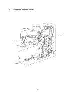
Page 28: ... 26 3 LEAD WIRE ARRANGEMENT ...
Page 57: ...PE 300S H8080132 ...


