- 18 -
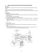
54. Attach tension pulley assembly with Allen screw.
55. Set feed link assembly into arm. Attach horizontal feed shaft and fasten with screw. (Be sure to attach one
poly washer each to both top and bottom of feed gear.)
56. Insert guide pin holder assembly pin into groove of vertical feed stand. Attach guide pin holder assembly with
screw. After assembling, attach spring between the recessed part of the guide pin holder and the hole on the
horizontal feed stand.
57. Attach eccentric collar to up-down feed arm assembly. Secure with screw. (Be sure to add poly washer
between up-down feed arm and eccentric collar.)
58. Attach drop lever spring between lever and hook of drop holder.
59. Run timing belt between initial plate and FPM gear shaft. Line up indicator marks on FPM gear and feed
gear, and set gears. Attach FPM assembly with 2 screws. (see page 43 of adjustment procedures.)
60. Run timing belt to outer rotary hook assembly. Add washers (2 on bottom and one on top), insert outer rotary
hook shaft and fasten with screw.
61. Run timing belt around vertical shaft assembly and attach vertical shaft assembly with 2 bushing presser and
2 screws.
62. Position so that both base line of outer rotary hook pulley and foundation hole of vertical shaft pulley are
faced towards front of sewing machine and attach timing belt. (see page 31 of adjustment procedures)
63. Adjust tension of timing belt. (see page 30 of adjustment procedures)
64. Screw on A and B set plates.
65. Attach thread tension unit holder (with thread tension assembly and handle attached) with 2 screws.
66. Attach needle plate. Adjust height and alignment of presser foot. (see page 37 of adjustment procedures)
After completing adjustments, remove needle plate.
Assembly Points
54. Loosely fasten tension pulley to line up with center of screw.
56. Move feed gears back and forth. Make sure that movement is smooth.
57. Attach eccentric collar so that the long slit is level with the right side.
60. Make sure that outer rotary hook assembly rotates freely.
61. Lift out timing belt and make sure that vertical shaft rotates freely.
65. Fix point of thread tension plate A of thread tension assembly into rectangular hole of thread tension plate
B. (see diagram A)
After putting together, raise and lower presser foot lift to check that thread tension disk opens and closes.
Summary of Contents for PE-300S
Page 1: ... 2 1999 ...
Page 4: ... 2 1 MECHANICAL CHART EMBROIDERY UNIT MECHANISM ...
Page 6: ... 4 3 ELECTRONIC PARTS ARRANGEMENT CHART ...
Page 7: ... 5 4 CONTROL SYSTEM BLOCK DIAGRAM ...
Page 11: ... 9 9 1 1 9 9 8 7 7 3 3 6 6 2 2 3 1 1 9 5 5 5 ...
Page 13: ... 11 12 11 17 20 20 15 16 19 20 18 13 14 10 10 ...
Page 15: ... 13 25 2 25 1 23 36 29 29 37 32 22 22 24 24 27 27 30 30 31 31 33 33 34 32 28 36 35 26 ...
Page 17: ... 15 39 39 38 ...
Page 19: ... 17 Diagram A 45 1 45 2 42 53 48 52 49 50 43 42 41 44 47 47 46 40 51 ...
Page 21: ... 19 Diagram A 55 60 56 54 58 64 64 65 61 61 59 59 54 57 ...
Page 23: ... 21 diagram A 74 69 69 68 69 75 73 72 70 67 67 ...
Page 25: ... 23 77 78 84 68 84 78 78 79 86 86 84 ...
Page 27: ... 25 5 3 2 2 2 2 3 4 1 5 ...
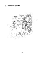
Page 28: ... 26 3 LEAD WIRE ARRANGEMENT ...
Page 57: ...PE 300S H8080132 ...


