- 42 -
16.
SETTING Z GEAR
STANDARD
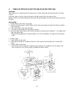
Line up indicator marks on release cam and ZPM gear evenly with mark on shaft.
Line up indicator marks on ZPM and Z gears, and set gears.
ADJUSTMENT
(release cam)
1.
Loosen screw on release cam.
2.
Align indicator marks on release cam and ZPM gear to mark on shaft.
3.
Tighten screw on release cam.
* When doing this, make sure there is clearance between the release cam and Z pulse motor.
(Z gear)
4.
Line up indicator marks on ZPM gear and Z gear, and attach Z gear.
Adjustment Points
(1) If release cam indicator marks do not line up properly, thread tension disk may fail to open during long
jumps in embroidery (when embroidery hoop moves over a substantial distance) resulting in possible
thread and needle breakage.
(2) If ZPM gear and Z gear indicator marks do not line up, it could result in unstable needle position, needle
breakage, incorrect stitch width, and faulty embroidery.
Z gear
Line up indicator marks
ZPM gear
ZPM gear
Release cam
Line up to indicator
mark on shaft
Clearance
Summary of Contents for PE-300S
Page 1: ... 2 1999 ...
Page 4: ... 2 1 MECHANICAL CHART EMBROIDERY UNIT MECHANISM ...
Page 6: ... 4 3 ELECTRONIC PARTS ARRANGEMENT CHART ...
Page 7: ... 5 4 CONTROL SYSTEM BLOCK DIAGRAM ...
Page 11: ... 9 9 1 1 9 9 8 7 7 3 3 6 6 2 2 3 1 1 9 5 5 5 ...
Page 13: ... 11 12 11 17 20 20 15 16 19 20 18 13 14 10 10 ...
Page 15: ... 13 25 2 25 1 23 36 29 29 37 32 22 22 24 24 27 27 30 30 31 31 33 33 34 32 28 36 35 26 ...
Page 17: ... 15 39 39 38 ...
Page 19: ... 17 Diagram A 45 1 45 2 42 53 48 52 49 50 43 42 41 44 47 47 46 40 51 ...
Page 21: ... 19 Diagram A 55 60 56 54 58 64 64 65 61 61 59 59 54 57 ...
Page 23: ... 21 diagram A 74 69 69 68 69 75 73 72 70 67 67 ...
Page 25: ... 23 77 78 84 68 84 78 78 79 86 86 84 ...
Page 27: ... 25 5 3 2 2 2 2 3 4 1 5 ...
Page 28: ... 26 3 LEAD WIRE ARRANGEMENT ...
Page 57: ...PE 300S H8080132 ...


