


3-26
Confidential
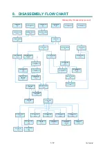
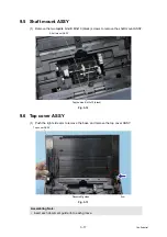
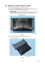
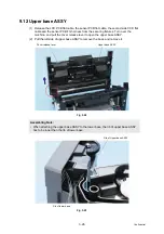
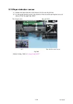
9.12 Upper base ASSY
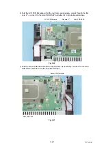
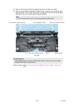
(1) Release the LCD PCB flat cable, the sensor PCB flat cable, the second side CCD flat
cable and the sensor PCB FG harness from the securing fixtures. Turn over the
machine, and pull the cover release lever to open the upper base ASSY.
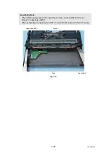
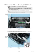
(2) Pull the left side of upper base ASSY to remove the boss, and remove it.
Fig. 3-28
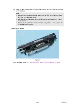
Fig. 3-29
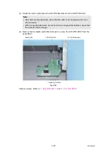
Assembling Note:
• When attaching the upper base ASSY to the lower base, the rib of upper base ASSY
has to be inner than the rib of lower base.
Upper base ASSY
Cover release lever
Rib of lower base
Rib of Upper base ASSY
Summary of Contents for PDS-5000
Page 23: ...2 4 Confidential 2 2 Document Feed Path Fig 2 2 Front side Document feed path Back side ...
Page 45: ...3 2 Confidential 2 PACKING Fig 3 1 ...
Page 48: ...3 5 Confidential 5 LUBRICATION There are no parts that require lubrication ...
Page 49: ...3 6 Confidential 6 OVERVIEW OF GEARS Left side Fig 3 3 Right side Fig 3 4 ...
Page 138: ...5 1 Confidential CHAPTER 5 SERVICE FUNCTIONS Service mode is not equipped with this product ...


