


3-23
Confidential
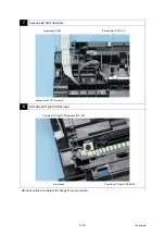
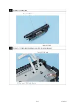
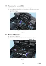
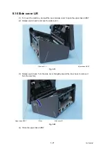
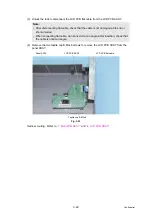
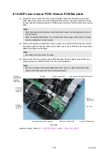
(3) Disconnect the feed motor harness, the pick-up motor harness, the first side LED light
PCB harness, the sensor PCB flat cable, the LCD PCB flat cable, the second side CCD
flat cable, and the first side CCD flat cable. Pull out each flat cable from each flat core.
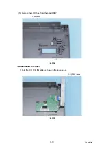
(4) Remove the main PCB ASSY.
(5) Remove each flat cable from the double-sided tape.
Fig. 3-23
Harness routing: Refer to
,
and
.
Note:
• When disconnecting each flat cable, unlock each lock to disconnect them.
• After disconnecting flat cables, check that each cable is not damaged at its end or
short-circuited.
• When connecting flat cables, do not insert them at an angle. After insertion, check
that the cables are not at an angle.
Note:
• Be sure to replace the double-sided tape with a new one, after taking off the flat
cable from the double-sided tape.
Note:
• Be careful not to damage the fan on the back of main PCB.
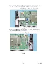
Main PCB
ASSY
First side LED light PCB
harness (RD, BK)
Sensor PCB FG
harness (BK)
Multi-feed sensor PCB
flat cable (Receive)
First side CCD
flat cable
Sensor PCB
flat cable
LCD PCB
flat cable
Feed motor harness
(RD, YW, BR, BK)
Pick-up motor harness
(RD, YW, BR, BK)
Second side
CCD flat cable
Summary of Contents for PDS-5000
Page 23: ...2 4 Confidential 2 2 Document Feed Path Fig 2 2 Front side Document feed path Back side ...
Page 45: ...3 2 Confidential 2 PACKING Fig 3 1 ...
Page 48: ...3 5 Confidential 5 LUBRICATION There are no parts that require lubrication ...
Page 49: ...3 6 Confidential 6 OVERVIEW OF GEARS Left side Fig 3 3 Right side Fig 3 4 ...
Page 138: ...5 1 Confidential CHAPTER 5 SERVICE FUNCTIONS Service mode is not equipped with this product ...


