


App.
4-16
Confidential
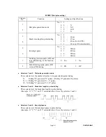
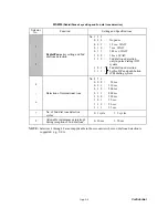
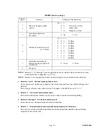
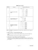
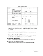
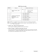
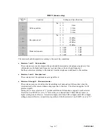
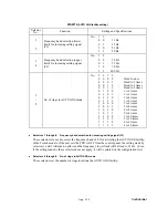
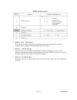
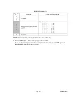
WSW12
(Signal detection condition setting)
Selector
No.
Function
Setting and Specifications
1
2
Min. detection period required
for interpreting incoming
calling signal (CI) as OFF
No. 1
2
0
0
:
1500 ms
0 1 : 500
ms
1 0 : 700
ms
1 1 : 900
ms
3
4
Max. detection period for
incoming calling signal (CI)
being OFF
No. 3
4
0
0
: 6 sec.
0
1
: 7 sec.
1
0
: 9 sec.
1 1 : 11
sec.
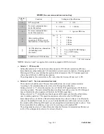
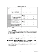
5
6
Min. detection period required
for acknowledging incoming
calling signal (CI) as ON
No. 5
6
0
0
: 800 ms (1000 ms*)
0 1 : 200
ms
1 0 : 250
ms
1 1 : 150
ms
7
Line connection timing
(Not used.)
0:
Ringer-OFF 1:
Ringer-ON
period
(default)
period
8 Not
used.
*1000 ms in Chinese models.
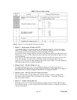
Selectors 1 through 4: Min. detection period required for interpreting incoming calling signal (CI) as
OFF
Max. detection period for incoming calling signal (CI) being OFF
If the machine detects the OFF state of a CI signal for the period greater than the value set by
selectors 1 and 2 and less than the value set by selectors 3 and 4, it interprets the CI signal as OFF.
Selectors 5 and 6: Min. detection period required for acknowledging incoming calling signal (CI) as
ON
These selectors set the period required to make the machine acknowledge itself to be called. That
is, if the machine continuously detects a CI signal with the frequency set by selectors 1 through 4
on WSW14 during the period set by these selectors 5 and 6, then it acknowledges the call.
Summary of Contents for MFC-9420CN
Page 1: ...Confidential FACSIMILE EQUIPMENT SERVICE MANUAL MODELS MFC 9420CN ...
Page 16: ...Confidential CHAPTER 1 PARTS NAMES FUNCTIONS ...
Page 22: ...Confidential CHAPTER 2 SPECIFICATIONS ...
Page 33: ...Confidential CHAPTER 3 THEORY OF OPERATION ...
Page 48: ...Confidential 3 1 4 CBV DBV Fig 3 16 Y M C K Fig 3 17 ...
Page 69: ...Confidential 3 3 5 Fig 3 35 ...
Page 73: ...Confidential 3 3 9 3 Interface Circuit Printer side Fig 3 38 ...
Page 82: ...Confidential CHAPTER 4 TRANSFER OF DATA LEFT IN THE MACHINE TO BE SENT FOR REPAIR ...
Page 85: ...Confidential 4 2 Cover page sample End page sample Fig 4 1 ...
Page 86: ...Confidential CHAPTER 5 DISASSEMBLY REASSEMBLY AND LUBRICATION ...
Page 94: ...Confidential 5 5 5 1 1 AC Cord 1 Disconnect AC cord from the machine Fig 5 1 AC cord Machine ...
Page 175: ...Confidential CHAPTER 6 ADJUSTMENTS AND UPDATING OF SETTINGS REQUIRED AFTER PARTS REPLACEMENT ...
Page 203: ...Confidential CHAPTER 7 CLEANING ...
Page 205: ...Confidential CHAPTER 8 MAINTENANCE MODE ...
Page 213: ...8 6 Confidential Fig 8 2 Scanning Compensation Data List a b c d e f g h i j k l m n q ...
Page 224: ...8 17 Confidential Cover page sample End page sample Fig 8 8 ...
Page 255: ...Confidential CHAPTER 9 ERROR INDICATION AND TROUBLESHOOTING ...
Page 279: ...Confidential 9 23 2 Image failure 1 2 3 4 5 6 7 8 9 10 11 12 13 14 ...
Page 280: ...Confidential 9 24 15 a 15 b 16 17 18 19 20 21 22 23 24 25 Fig 9 1 ...
Page 325: ...App 1 5 Confidential 6 Transfer Unit X X X X X X 7 1 2 3 Location SERIAL NO YEAR MONTH DATE ...
Page 398: ...B Power Supply PCB 100V 127V Confidential ...


