


Confidential
5-53
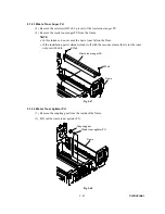
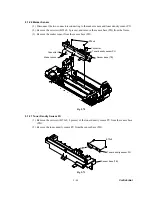
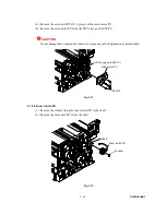
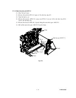
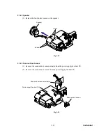
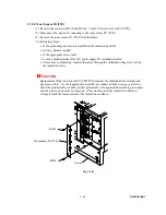
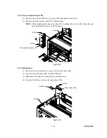
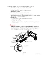
5.1.41 Toner Sensor PU (TPD)
(1) Remove the setscrew (BT3x8 and BT3x6, 1each) of the toner sensor PU (TPD).
(2) Remove the connector (inside the frame) connecting to the toner sensor PU (TPD).
(3) Remove the toner sensor PU (TPD) from the frame.
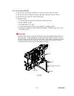
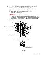
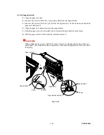
<Confirmation Items>
•
Is the grounding wire securely installed to the indicated position?
•
Isn't any harness caught?
•
Is the appropriate screw used?
•
Is each output terminal of the HV power supply PU installed properly?
•
After above confirmation, confirm the safety through the withstand voltage test or with
the insulation tester.
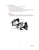
CAUTION
Replacement of the toner sensor PU (TPD/TTR) requires the substantial disassembly and
also reassembly. As the inappropriate assembly procedures and the wrong use of screws
affect the product safety and the product performance, the appropriate assembly procedures
and the caution items must be respected. (This work requires the insulation withstand
voltage test and the measurement of the insulation resistance.)
Fig. 5-86
BT3x8
BT3x6
Toner sensor PU (TPD)
Frame
Connector
Summary of Contents for MFC-9420CN
Page 1: ...Confidential FACSIMILE EQUIPMENT SERVICE MANUAL MODELS MFC 9420CN ...
Page 16: ...Confidential CHAPTER 1 PARTS NAMES FUNCTIONS ...
Page 22: ...Confidential CHAPTER 2 SPECIFICATIONS ...
Page 33: ...Confidential CHAPTER 3 THEORY OF OPERATION ...
Page 48: ...Confidential 3 1 4 CBV DBV Fig 3 16 Y M C K Fig 3 17 ...
Page 69: ...Confidential 3 3 5 Fig 3 35 ...
Page 73: ...Confidential 3 3 9 3 Interface Circuit Printer side Fig 3 38 ...
Page 82: ...Confidential CHAPTER 4 TRANSFER OF DATA LEFT IN THE MACHINE TO BE SENT FOR REPAIR ...
Page 85: ...Confidential 4 2 Cover page sample End page sample Fig 4 1 ...
Page 86: ...Confidential CHAPTER 5 DISASSEMBLY REASSEMBLY AND LUBRICATION ...
Page 94: ...Confidential 5 5 5 1 1 AC Cord 1 Disconnect AC cord from the machine Fig 5 1 AC cord Machine ...
Page 175: ...Confidential CHAPTER 6 ADJUSTMENTS AND UPDATING OF SETTINGS REQUIRED AFTER PARTS REPLACEMENT ...
Page 203: ...Confidential CHAPTER 7 CLEANING ...
Page 205: ...Confidential CHAPTER 8 MAINTENANCE MODE ...
Page 213: ...8 6 Confidential Fig 8 2 Scanning Compensation Data List a b c d e f g h i j k l m n q ...
Page 224: ...8 17 Confidential Cover page sample End page sample Fig 8 8 ...
Page 255: ...Confidential CHAPTER 9 ERROR INDICATION AND TROUBLESHOOTING ...
Page 279: ...Confidential 9 23 2 Image failure 1 2 3 4 5 6 7 8 9 10 11 12 13 14 ...
Page 280: ...Confidential 9 24 15 a 15 b 16 17 18 19 20 21 22 23 24 25 Fig 9 1 ...
Page 325: ...App 1 5 Confidential 6 Transfer Unit X X X X X X 7 1 2 3 Location SERIAL NO YEAR MONTH DATE ...
Page 398: ...B Power Supply PCB 100V 127V Confidential ...


