PREFACE
This service manual contains basic information required for after-sales service of the laser printer
(hereinafter referred to as “this machine” or “the printer”). This information is vital to the service
technician in maintaining the high printing quality and performance of the printer.
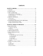
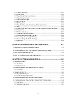
This manual consists of the following chapters:
CHAPTER
I :
GENERAL
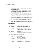
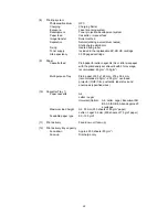
Features, specifications, etc.
CHAPTER II
:
THEORY OF OPERATION
Basic operation of the mechanical system and the electrical system, and their timing.
CHAPTER III :
ELECTRICAL SYSTEM
Theory of the electronics circuit
CHAPTER IV :
MECHANICAL SYSTEM
Requirements for a suitable location, disassembling and reassembling procedure of
mechanical system.
CHAPTER V :
MAINTENANCE AND SERVICING
Parts replacement schedule, list of tools, lubricants and cleaners.
CHAPTER VI :
TROUBLESHOOTING
Reference values and adjustment, troubleshooting for image defects, troubleshooting
for malfunctions, etc.
APPENDICES : Engin Block Daiagram, PCB Circuitry Diagrams, etc.
Information in this manual is subject to change due to improvement or re-design of the product.
All relevant information in such cases will be supplied in service information bulletins (Technical
Information).
A thorough understanding of this printer, based on information in this service manual and service
information bulletins, is required for maintaining its quality performance and fostering the pratical
ability to find the cause of troubles.
Summary of Contents for HL-2060
Page 1: ...MECHANICS ELECTRONICS SERVICE MANUAL LASER PRINTER ...
Page 41: ...III 8 A B F C D E 1 E 2 E 3 E 4 E 5 F Figure 3 7 Paper Feed Size SW PCB Circuit ...
Page 129: ...VII 16 Test for memory MEMORY DISPLAY MEMORY DEBUG MEMORY TEST exit MENU ...
Page 137: ...Appendix A 3 Main PCB Circuitry Diagram 1 7 CODE UK4058000 B512006 CIR 1 7 NAME A 3 ...
Page 138: ...Appendix A 4 Main PCB Circuitry Diagram 2 7 CODE UK4058000 B512006 CIR 2 7 NAME A 4 ...
Page 139: ...Appendix A 5 Main PCB Circuitry Diagram 3 7 CODE UK4058000 B512006 CIR 3 7 NAME A 5 ...
Page 140: ...Appendix A 6 Main PCB Circuitry Diagram 4 7 CODE UK4058000 B512006 CIR 4 7 NAME A 6 ...
Page 141: ...Appendix A 7 Main PCB Circuitry Diagram 5 7 CODE UK4058000 B512006 CIR 5 7 NAME A 7 ...
Page 142: ...Appendix A 8 Main PCB Circuitry Diagram 6 7 CODE UK4058000 B512006 CIR 6 7 NAME A 8 ...
Page 143: ...Appendix A 9 Main PCB Circuitry Diagram 7 7 CODE UK4058000 B512006 CIR 7 7 NAME A 9 ...
Page 144: ...Appendix A 10 Control Panel PCB Circuitry Diagram 1 1 CODE UK4077000 B512005 CIR NAME A 10 ...
Page 145: ...Appendix A 11 Laser LD PCB Circuitry Diagram 1 1 CODE UK3253000 B48K253 CIR NAME A 11 ...
Page 147: ...June 98 54T046NE0 HL2060 ...


