VII-5
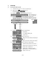
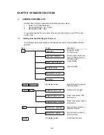
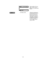
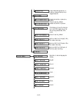
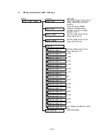
10mm grid pattern sheet
for offset print check
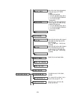
Adjust the top margin for feeding
from MP tray in the range from -
2.0 mm to +2.0 mm, by 0.5 mm
Adjust the top margin for feeding
from cassette tray in the range
from -2.0 mm to +2.0 mm, by 0.5
mm
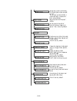
Adjust the toner fixing temperature
for transparencies at 20 PPM
printing.
•
Standard tenperature
•
- 5 C from standard temperature
•
+ 5 C from standard temperature
•
+ 10 C from standard
temperature
Adjust the toner fixing temperature
for ragular paper at 20 PPM
printing.
•
Standard tenperature
•
- 5 C from standard temperature
•
+ 5 C from standard temperature
•
+ 10 C from standard
temperature
Adjust the toner fixing temperature
for thick paper at 20 PPM printing.
•
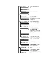
Standard tenperature
•
- 5 C from standard temperature
•
+ 5 C from standard temperature
•
+ 10 C from standard
temperature
Adjust the toner fixing temperature
for ragular paper at 10 PPM
printing.
•
Standard tenperature
•
- 5 C from standard temperature
•
+ 5 C from standard temperature
•
+ 10 C from standard
temperature
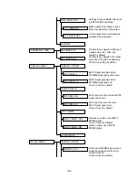
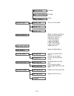
TEST PRN=GRID2
ENGINE ADJUST
MP-CAS ADJUST
MP OFFSET
CAS OFFSET
exit
PRESSURE TEMPER.
TRANS 20PPM
REGUL 20PPM
THICK 20PPM
TRANS 10PPM
Summary of Contents for HL-2060
Page 1: ...MECHANICS ELECTRONICS SERVICE MANUAL LASER PRINTER ...
Page 41: ...III 8 A B F C D E 1 E 2 E 3 E 4 E 5 F Figure 3 7 Paper Feed Size SW PCB Circuit ...
Page 129: ...VII 16 Test for memory MEMORY DISPLAY MEMORY DEBUG MEMORY TEST exit MENU ...
Page 137: ...Appendix A 3 Main PCB Circuitry Diagram 1 7 CODE UK4058000 B512006 CIR 1 7 NAME A 3 ...
Page 138: ...Appendix A 4 Main PCB Circuitry Diagram 2 7 CODE UK4058000 B512006 CIR 2 7 NAME A 4 ...
Page 139: ...Appendix A 5 Main PCB Circuitry Diagram 3 7 CODE UK4058000 B512006 CIR 3 7 NAME A 5 ...
Page 140: ...Appendix A 6 Main PCB Circuitry Diagram 4 7 CODE UK4058000 B512006 CIR 4 7 NAME A 6 ...
Page 141: ...Appendix A 7 Main PCB Circuitry Diagram 5 7 CODE UK4058000 B512006 CIR 5 7 NAME A 7 ...
Page 142: ...Appendix A 8 Main PCB Circuitry Diagram 6 7 CODE UK4058000 B512006 CIR 6 7 NAME A 8 ...
Page 143: ...Appendix A 9 Main PCB Circuitry Diagram 7 7 CODE UK4058000 B512006 CIR 7 7 NAME A 9 ...
Page 144: ...Appendix A 10 Control Panel PCB Circuitry Diagram 1 1 CODE UK4077000 B512005 CIR NAME A 10 ...
Page 145: ...Appendix A 11 Laser LD PCB Circuitry Diagram 1 1 CODE UK3253000 B48K253 CIR NAME A 11 ...
Page 147: ...June 98 54T046NE0 HL2060 ...

