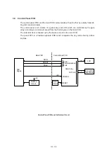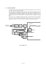
III –
23
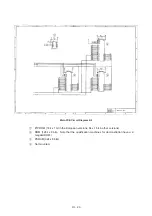
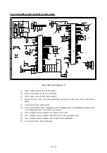
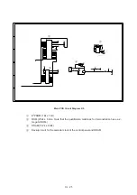
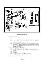
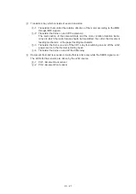
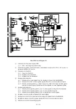
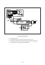
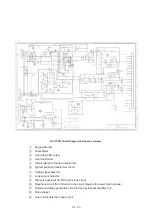
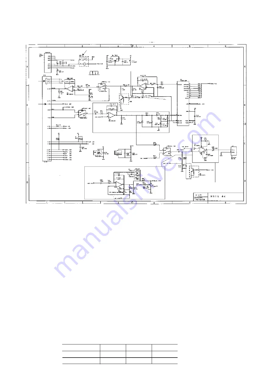
Main PCB Circuit Diagram 4/4
1
Connector for the power supply PCB
1
-1: CR1, recording head on/off relay
2
3-terminal regulator which eliminates unstabilized components of the +8V source to
generate stabilized 5V source.
3
Connector for the NCU
3
-1: Power for the NCU
3
-2: Signals from the telephone
4
Analog signal selectors
4
-1: Selects either input signals from the handset or those from the MODEM.
4
-2: Selects either RL1 or RL2 signals inputted from the communications network.
4
-3: Selects either sound signals (e.g., alarm beeps, key clicks and ringer sounds) generated
by the FAX engine or signals selected by
4
-2.
5
Amplifier circuit for signals outputted from the MODEM.
6
Analog front end IC which processes the analog I/O signals from/to the MODEM.
7
Amplifier & shaper circuit for signals inputted from the communications network.
8
Telephone circuit for transmitting signals.
9
Speaker amplifier circuit which amplifies sounds issued from the above analog signal
selector
4
-3 and feeds them to the speaker.
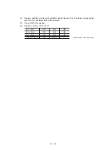
:
Connector for the speaker
a
Speaker volume control circuit
a
-1: VOL1
OFF
ON
ON
a
-2: VOL2
OFF
OFF
ON
Speaker volume
High
Medium
Low
(ON: Closed OFF: Opened)
1
1
-1
2
3
3
-2
3
-1
4
-1
4
-2
4
-3
5
6
7
8
9
:
a
a
-1
a
-2
Summary of Contents for FAX-270MC
Page 4: ...CHAPTER I GENERAL DESCRIPTION ...
Page 11: ...CHAPTER II INSTALLATION ...
Page 12: ...CHAPTER III THEORY OF OPERATION ...
Page 49: ...CHAPTER IV DISASSEMBLY REASSEMBLY AND LUBRICATION ...
Page 86: ...IV 36 4 Cutter unit Cutter unit A A A A ...
Page 87: ...CHAPTER V MAINTENANCE MODE ...
Page 140: ...CHAPTER VI ERROR INDICATION AND TROUBLESHOOTING ...
Page 157: ...March 98 5X1S112 Printed in Japan ...
Page 173: ...D POWER SUPPLY 100 120 V U S A CANADA ...
Page 174: ...POWER SUPPLY 200 240 V EUROPE SOUTH AMERICA D ...
Page 175: ...POWER SUPPLY 200 240 V GULF ASIA CHINA D ...
Page 192: ...D POWER SUPPLY 100 120 V U S A CANADA ...
Page 193: ...POWER SUPPLY 200 240 V EUROPE SOUTH AMERICA D ...
Page 194: ...POWER SUPPLY 200 240 V GULF ASIA CHINA D ...
Page 195: ...FACSIMILE EQUIPMENT PARTS REFERENCE LIST MODEL FAX170 190 190 Plus 195 ...
Page 198: ......
Page 203: ......
Page 206: ...Remarks 8 8 8 8 8 8 9 9 8 8 8 8 8 8 0 1 0 1 Brother Technical Information FAX98250 4 ...
Page 208: ... 8 01 8 01 8 8 8 8 0 1 0 1 8 8 8 8 Brother Technical Information FAX99102 6 ...
Page 220: ......

