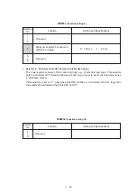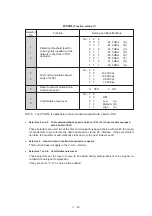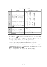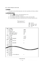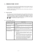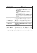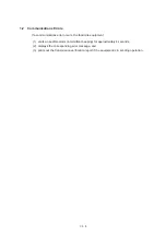
VI –
3
82
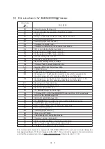
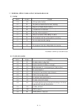
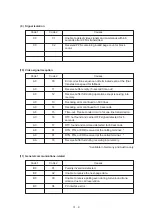
Recording paper feeding error.
87
Fails to complete the sequence of recording operation.
( 89
Cutter jam. )
8A
Wrong or weak contact of the recording head connectors.
( 8B
Recording head overheat. )
( A1
Recording paper cover opened. )
( A2
Document too long to scan. )
( A3
Document not detected by the document rear sensor. )
( A4
50% or more faulty of white level data. )
A5
Faulty operation of DMA0 during scanning.
A6
Faulty operation of DMA1 during scanning.
A7
One-line feeding time-out error.
A8
One-line scanning time-out error.
A9
Abnormal scanning reference voltage.
AB
Document feed-in amount measuring error.
AC
Less than 50% faulty of white level data.
B1
CODEC LSI error.
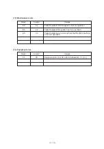
( B9
Light emission intensity error of the LED array. )
( BA
Scanning error: The left-hand black reference line which is marked on the
document pressure bar for scanning width setting is not detected.)
( BB
Scanning error: The right-hand black reference line which is marked on the
document pressure bar for scanning width setting is not detected.)
( BC
Scanning error: Reduction miss)
( BD
Scanning error: Enlargement miss)
( BE
Abnormal clamp BWM value)
D1
The MODEM setup bit sticks to High.
D2
CTS stays OFF or ON if the MODEM RTS is turned ON or OFF, respectively.
D3
Bit B1A of the MODEM stays OFF.
D4
Bit RX of the MODEM stays OFF.
D5
The MODEM fails to complete the command transmission sequence.
D6
No MODEM interrupt for 60 seconds.
E1
Microprocessor (MPU) error on the control panel PCB.
( E4
Out of recording paper. )
( E5
Recording paper set error. )
E6
Write error in E
2
PROM.
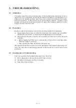
E8
Data scanning error during transmission.
( EA
Document removed at phase B.)
F3
Voice message recording or playing-back not started.
F5
EOL not found in page memory transmission mode.
FF
Interface error of page memory command.
[ 2 ]
Error codes shown in the “MACHINE ERROR XX” message
Error factor
Error Code
xx
(Hex.)
Error codes in parentheses do not appear in the “MACHINE ERROR XX”, since those errors are displayed as
messages described in "[ 1 ] Error messages on the LCD." Those error codes appear in the communications
error list if an equipment error occurs during communications. Refer to Section 1.2, (13).
Summary of Contents for FAX-270MC
Page 4: ...CHAPTER I GENERAL DESCRIPTION ...
Page 11: ...CHAPTER II INSTALLATION ...
Page 12: ...CHAPTER III THEORY OF OPERATION ...
Page 49: ...CHAPTER IV DISASSEMBLY REASSEMBLY AND LUBRICATION ...
Page 86: ...IV 36 4 Cutter unit Cutter unit A A A A ...
Page 87: ...CHAPTER V MAINTENANCE MODE ...
Page 140: ...CHAPTER VI ERROR INDICATION AND TROUBLESHOOTING ...
Page 157: ...March 98 5X1S112 Printed in Japan ...
Page 173: ...D POWER SUPPLY 100 120 V U S A CANADA ...
Page 174: ...POWER SUPPLY 200 240 V EUROPE SOUTH AMERICA D ...
Page 175: ...POWER SUPPLY 200 240 V GULF ASIA CHINA D ...
Page 192: ...D POWER SUPPLY 100 120 V U S A CANADA ...
Page 193: ...POWER SUPPLY 200 240 V EUROPE SOUTH AMERICA D ...
Page 194: ...POWER SUPPLY 200 240 V GULF ASIA CHINA D ...
Page 195: ...FACSIMILE EQUIPMENT PARTS REFERENCE LIST MODEL FAX170 190 190 Plus 195 ...
Page 198: ......
Page 203: ......
Page 206: ...Remarks 8 8 8 8 8 8 9 9 8 8 8 8 8 8 0 1 0 1 Brother Technical Information FAX98250 4 ...
Page 208: ... 8 01 8 01 8 8 8 8 0 1 0 1 8 8 8 8 Brother Technical Information FAX99102 6 ...
Page 220: ......

