V –
12
* PABX: Private automatic branch exchange
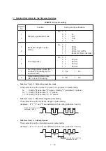
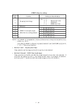
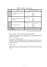
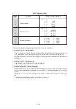
NOTE: Selectors 2 through 4 and 6 through 8 are not applicable where no PABX is installed.
●
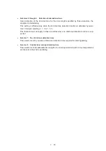
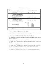
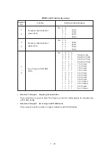
Selectors 1 and 5: CNG detection when sharing a modular wall socket with a telephone
These selectors determine whether or not the equipment detects a CNG signal when a line
is connected to a telephone sharing a modular wall socket with the equipment. If these se-
lectors are set to “0,0,” the equipment does not detect CNG. If set to other selector values,
the equipment interprets CNG as an effective signal upon detection of CNG signals by the
number of cycles specified by these selectors and then starts FAX reception.
Selector
No.1
No. 5
Cycle
0 (A)
0 (A)
No detection
0 (A)
1 (B)
One cycle
1 (B)
0 (A)
1.5 cycles
1 (B)
1 (B)
2 cycles
●
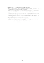
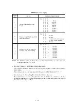
Selectors 2 through 4:
Min. detection time length of PABX dial tone, required for starting
dialing
Upon detection of the PABX dial tone for the time length set by these selectors, the equip-
ment starts dialing.
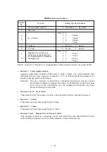
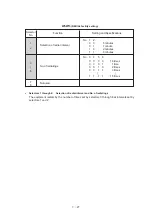
These selectors are effective only when both selectors 6 and 7 are set to "1" (Detection).
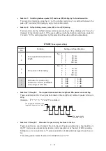
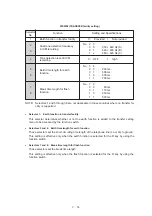
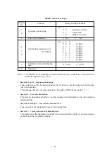
WSW03
(PABX* mode setting)
Function
Selector
No.
Setting and Specifications
CNG detection when sharing a
modular wall socket with a telephone
CNG detection when sharing a
modular wall socket with a telephone
1
0:
A
1:
B
2
|
4
Min. detection time length of
PABX* dial tone, required for
starting dialing
No. 2
3
4
0
0
0
:
50 ms
0
0
1
:
210 ms
0
1
0
:
500 ms
0
1
1
:
800 ms
1
0
0
:
900 ms
1
0
1
:
1.5 sec.
1
1
0
:
2.0 sec.
1
1
1
:
2.5 sec.
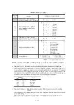
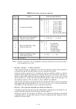
5
0:
A
1:
B
8
"R" key function
0:
1st dial tone
1:
No 1st dial
detection add
tone detection
No. 6
7
0
0
:
No detection
(3.5 sec. WAIT)
0
1
:
No detection
(5 sec. WAIT)
1
0
:
No detection
(7 sec. WAIT)
1
1
:
Detection
(Frequency only)
Dial tone detection in PABX*
6
7
Summary of Contents for FAX-270MC
Page 4: ...CHAPTER I GENERAL DESCRIPTION ...
Page 11: ...CHAPTER II INSTALLATION ...
Page 12: ...CHAPTER III THEORY OF OPERATION ...
Page 49: ...CHAPTER IV DISASSEMBLY REASSEMBLY AND LUBRICATION ...
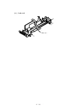
Page 86: ...IV 36 4 Cutter unit Cutter unit A A A A ...
Page 87: ...CHAPTER V MAINTENANCE MODE ...
Page 140: ...CHAPTER VI ERROR INDICATION AND TROUBLESHOOTING ...
Page 157: ...March 98 5X1S112 Printed in Japan ...
Page 173: ...D POWER SUPPLY 100 120 V U S A CANADA ...
Page 174: ...POWER SUPPLY 200 240 V EUROPE SOUTH AMERICA D ...
Page 175: ...POWER SUPPLY 200 240 V GULF ASIA CHINA D ...
Page 192: ...D POWER SUPPLY 100 120 V U S A CANADA ...
Page 193: ...POWER SUPPLY 200 240 V EUROPE SOUTH AMERICA D ...
Page 194: ...POWER SUPPLY 200 240 V GULF ASIA CHINA D ...
Page 195: ...FACSIMILE EQUIPMENT PARTS REFERENCE LIST MODEL FAX170 190 190 Plus 195 ...
Page 198: ......
Page 203: ......
Page 206: ...Remarks 8 8 8 8 8 8 9 9 8 8 8 8 8 8 0 1 0 1 Brother Technical Information FAX98250 4 ...
Page 208: ... 8 01 8 01 8 8 8 8 0 1 0 1 8 8 8 8 Brother Technical Information FAX99102 6 ...
Page 220: ......

