Brooks Instrument Model 5866 Pressure Controller
1-4
When the pressure controller is used in the “downstream pressure
regulation” mode as shown in Figure 1-6, the pressure in the process
vessel will be constant independent of upstream variation, provided the
upstream pressure does not fall below the downstream setting. Pressure
measurement and control takes place at the inlet side of the pressure
vessel.
The most common application of the pressure controller is in conjunction
with a mass flow controller (refer to Figure 1-7). Mass flow controllers
accurately measure and control the required quantity of process gas flows.
In this figure, the mass flow controllers will supply the desired quantity and
mixture of process gas while the pressure controller will maintain the
desired reactor pressure by varying the gas outflow. This system allows
the process reactants to be varied while maintaining a constant reaction
pressure.
The Model 5866 Pressure Controller has proportional and integral control
action. The reset or integral control is combined with the proportional
control action (normally referred to as P.I. control). Both proportional band
(0.5% to 100%) and integration time (0.05 to 5 seconds) are customer
adjustable. Tuning of the pressure controller to perform as a stable
optimum for each application is performed in-process by adjusting easily
accessible P.I. action potentiometers (refer to Figure 1-4).
Note: The Controller Mode and valve type are determined at the time of
order. Mechanical parts must be changed to convert modes or valve types.
Figure 1-5. Model 5866 Upstream
Controller.
Figure 1-6. Model 5866
Downstream Controller.
Vessel
Model 5866
Pressure Controller
Vessel
Model 5866E
Pressure Controller
Summary of Contents for 5866
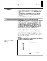
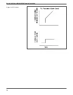
Page 20: ...3 3 Operation Figure 3 2 Proportional Control Figure 3 3 Integral Control ...
Page 21: ...Brooks Instrument Model 5866 Pressure Controller 3 4 Figure 3 4 P I Control ...
Page 23: ...Brooks Instrument Model 5866 Pressure Controller 4 2 ...
Page 32: ...5 9 Troubleshooting Figure 5 3 Valve Adjusting Spacer Locations ...
Page 34: ...5 11 Troubleshooting Figure 5 4 Valve Adjusting Spacer Locations Normally Open N O Valve ...
Page 43: ...Brooks Instrument Model 5866 Pressure Controller 6 6 ...
Page 45: ...Brooks Instrument Model 5866 Pressure Controller 7 2 Figure 7 1 Model 5866E Parts Drawing ...
Page 47: ...Brooks Instrument Model 5866 Pressure Controller 7 4 Figure 7 2 Model 5866M Parts Drawing ...
Page 48: ...7 5 Parts List Table 7 3 Model 5866M Parts List ...
Page 49: ...Brooks Instrument Model 5866 Pressure Controller 7 6 ...
Page 65: ......


