background image

Brooks Instrument Model 5866 Pressure Controller

1-4

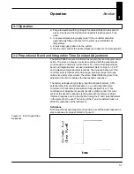
When the pressure controller is used in the “downstream pressure
regulation” mode as shown in Figure 1-6, the pressure in the process
vessel will be constant independent of upstream variation, provided the
upstream pressure does not fall below the downstream setting. Pressure
measurement and control takes place at the inlet side of the pressure
vessel.

The most common application of the pressure controller is in conjunction
with a mass flow controller (refer to Figure 1-7). Mass flow controllers
accurately measure and control the required quantity of process gas flows.
In this figure, the mass flow controllers will supply the desired quantity and
mixture of process gas while the pressure controller will maintain the
desired reactor pressure by varying the gas outflow. This system allows
the process reactants to be varied while maintaining a constant reaction
pressure.

The Model 5866 Pressure Controller has proportional and integral control
action. The reset or integral control is combined with the proportional
control action (normally referred to as P.I. control). Both proportional band
(0.5% to 100%) and integration time (0.05 to 5 seconds) are customer
adjustable. Tuning of the pressure controller to perform as a stable
optimum for each application is performed in-process by adjusting easily
accessible P.I. action potentiometers (refer to Figure 1-4).

Note: The Controller Mode and valve type are determined at the time of
order. Mechanical parts must be changed to convert modes or valve types.

Figure 1-5. Model 5866 Upstream
Controller.

Figure 1-6. Model 5866
Downstream Controller.

Vessel

Model 5866

Pressure Controller

Vessel

Model 5866E

Pressure Controller

Summary of Contents for 5866

Page 1: ...Installation and Operation Manual X PR 5866E 5866M eng PN 541 C 005 AAA April 2008 Brooks Compact Pressure Controller Model 5866 Model 5866 ...

Page 2: ...In Line Filter 2 3 Electrical Interface 2 3 Remote Setpoint Command Input 2 3 Valve Override 2 5 Precision 5V Reference 2 5 Remote Transducer Input 2 5 Valve Test Point 2 5 Optional Valve Return 2 6 Section 3 Operation Operation 3 1 Proportional Band and Integration Time Constant Adjustment 3 1 Section 4 Maintenance General 4 1 Section 5 Troubleshooting General 5 1 Troubleshooting 5 1 Disassembly ...

Page 3: ...ctions and Settings 2 4 3 1 Error Signal Step Response 3 1 3 2 Proportional Control 3 3 3 3 Integral Control 3 3 3 4 P I Control 3 4 5 1 Torque Sequence for the Valve Retainer Plate 5 6 5 2 Adjustment Test Setup 5 7 5 3 Valve Adjusting Spacer Locations 5 9 5 4 Valve Adjusting Spacer Locations Normally Open N O Valve 5 11 5 5 Application Configuration 5 12 5 6 Example Application of Orifice Sizing ...

Page 4: ...ilicon chip refer to Figure 1 1 The chip consists of an anisotropically etched diaphragm with four piezo resistive resistors configured in a Wheatstone bridge etched into its surface refer to Figure 1 2 The mechanical deformation of this diaphragm results in an imbalance of the resistors which is proportional to pressure An amplifier provides output to the control circuit as well as the electrical...

Page 5: ...gure 1 2 Model 5866 Silicon Chip Configuration Figure 1 3 Model 5866 System Block Diagram Downstream version COMMAND INPUT VALVE OVERRIDE OPTIONAL Model 5866 VALVE DRIVE REMOTE TRANSDUCER INPUT COMPARISON AMPLIFIER CONTROL VALVE 5 VOLT REFERENCE VALVE OVERRIDE LOGIC COMMAND POT PRESSURE TRANSDUCER ...

Page 6: ...tlet A 0 50 12 7 1 50 38 0 5 23 133 0 3 00 76 2 15 Pin Male D Connector Upstream Outlet Downstream Inlet Proportional Adjustment P I Upstream Downstream Flow Indicator Label Valve Height w Downstream Adapter 14 3 6 39 10 0 71 18 0 2 58 65 4 8 32 UNC 2B x 1 4 Deep 2 Mounting Holes 1 50 38 0 Model 5866E Model 5866M 15 Position Male D Connector 71 18 0 Z 8 32 UNC x 1 4 Deep 2 Mounting Holes 39 9 9 28...

Page 7: ...ill maintain the desired reactor pressure by varying the gas outflow This system allows the process reactants to be varied while maintaining a constant reaction pressure The Model 5866 Pressure Controller has proportional and integral control action The reset or integral control is combined with the proportional control action normally referred to as P I control Both proportional band 0 5 to 100 a...

Page 8: ...he Normally Open valve may be specified when Safety Operation or Process considerations warrant this type of valve Remote Pressure Sensor Input allows the use of the integral control electronics and the valve to regulate the process pressure in response to the remote pressure transducer signal refer to Section 2 11 Voltage and Current Inputs Outputs Jumpers are provided on the PC board to allow 0 ...

Page 9: ...ommand potentiometer to generate a 0 5 V command signal 1 4 Specifications WARNING Do not operate this instrument in excess of the specifications listed below Failure to heed this warning can result in serious personal injury and or damage to the equipment Pressure Ranges 7 25 psia to 1450 psia full scale Elastomer Seals 7 25 psia to 72 5 psia full scale Metal Seals Model 5866E Reactor Mass Flow C...

Page 10: ...perature Coefficient 0 1 full scale C MaximumTransducer Pressure 21 75 psia for 0 14 5 psia range 108 5 psia for 14 5 72 5 psia range 435 psia for 72 5 290 psia range 1 450 psia for 290 1 450 psia range Maximum Design Pressure 1 450 psig 1 5 Controller Specifications Input Output Offset 0 2 full scale voltage 1 5 full scale current Proportional Gain Adjustable 1 to 200 IntegrationTime Adjustable 0...

Page 11: ...ndard Normally Closed Optional Normally Open Process Connections Standard 1 4 stainless steel compression fittings Optional 1 4 VCRTM 1 4 VCOTM 1 8 compression Electrical Connection 15 pin D Connector DA 15P Environmental Conditions Installation Category I Pollution Degree 2 Humidity 50 80 Relative Humidity Meter Altitude 6562 feet 2 000 meters For Indoor Use ONLY Mains supply voltage fluctuations...

Page 12: ...nimum Upon removal from storage a visual inspection should be conducted to verify the condition of the equipment is as received If the equipment has been in storage for an excess of ten 10 months or under conditions in excess of those recommended all pressure boundary seals should be replaced and the device subjected to a pneumatic pressure test in accordance with applicable vessel codes 2 3 Gener...

Page 13: ...eld is tied over 360 degrees to the shell at both ends This is mandatory to be in compliance with the EMC Directive 89 336 EEC Refer to Appendix A Recommended Installation Procedures a The Model 5866 should be located in a clean dry atmosphere relatively free from shock and vibration b Leave sufficient room for access to the electrical components c Install in such a manner that permits easy remova...

Page 14: ...lly replaced or cleaned 2 7 Electrical Interface To insure proper operation the Model 5866 must be connected per Figure 2 1 As a minimum the following connections must be made for new installations Pin Number Description 1 Command Common 2 or 4 Signal Output 5 15 Vdc Supply 6 15 Vdc Supply 8 Command Input 9 Supply Voltage Common 10 Voltage Signal Common 13 15 Vdc Supply Current I O Note The Comman...

Page 15: ...Brooks Instrument Model 5866 Pressure Controller 2 4 Figure 2 1 Customer Connections and Settings ...

Page 16: ... the valve override terminal b To close the valve apply 15 Vdc to the valve override terminal The valve override function is accessed from Terminal 12 refer to Figure 2 1 and Table 2 1 Note For normal operation Terminal 12 may be left open floating or grounded 2 10 Precision 5V Reference The Model 5866 is equipped with a precision 5 Vdc reference The reference is used internally for precise zero a...

Page 17: ...rmally Closed valve can be configured so the valve current can be returned to the power supply on a separate line This is recommended if the power supply lines are longer than 10 feet The feature is enabled by connecting Pin 3 of the D Connector to power supply common with a separate lead and moving Jumper J3 to the Position a ...

Page 18: ...o Figure 1 4 for P and I adjustment potentiometer locations The dynamic behavior of the control system is influenced by flow range pressure range fluid type orifice size and system volume Therefore Model 5866 may have to be adjusted in the field to achieve the best dynamic response The factory settings are typically proportional band minimum 0 5 potentiometer fully counterclockwise c c w and integ...

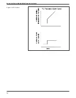
Page 19: ...ror is present Characteristics of P I Control By using both proportional and integral control actions rapid control can be achieved with out a steady state offset Refer to Figure 3 4 Typically there is a slight decrease in system stability due to the presence of the integral mode The dynamic response of the system is better than the response would be with integral alone Because the two controller ...

Page 20: ...3 3 Operation Figure 3 2 Proportional Control Figure 3 3 Integral Control ...

Page 21: ...Brooks Instrument Model 5866 Pressure Controller 3 4 Figure 3 4 P I Control ...

Page 22: ...nance 4 1 General No routine external maintenance is required for Brooks thermal mass flow controller If an in line filter is used for the Model 5866 the filtering element should periodically be replaced or cleaned Section 4 ...

Page 23: ...Brooks Instrument Model 5866 Pressure Controller 4 2 ...

Page 24: ...er appears to be functioning but cannot achieve set point verify that sufficient inlet pressure and pressure drop are available at the controller to provide the required flow 4 Verify that all user selectable jumpers are in their desired positions refer to Figure 2 1 WARNING If it becomes necessary to remove the controller from the system after exposure to toxic pyrophoric flammable or corrosive g...

Page 25: ...mbly The Model 5866 pressure controller may be disassembled in the field by the user for cleaning re ranging or servicing The disassembly procedures below detail the upstream control version of the Model 5866 with a Normally Closed control valve The procedures for the upstream control version and the Normally Open control valve are substantially the same Disassemble the controller as follows Note ...

Page 26: ...ignal follows setpoint at higher Leaky control valve Disassemble and repair valve Refer to Sections 5 3 and 5 4 commands but will not go to zero Excessive resistance in valve voltage return Reduce wiring resistance line Output signal follows setpoint at lower Insufficient inlet pressure or pressure drop Adjust pressures check calibration Refer to Section 5 1 commands but does not reach full scale ...

Page 27: ...hstand pressure of the transducer creating the need for adjustment or replacement Be sure the transducer needs to be removed before proceeding 11 Remove the two screws 3 from the base plate 27 then reinstall them 2 3 turns into the body Reinstall the valve stem 6 retaining plate 4 using the four hex socket screws 3 Cap the outlet port WARNING The screws 3 are to be reinstalled to prevent violent e...

Page 28: ...or thirty minutes prior to start up to prevent the formation of deposits 5 4 Assembly The assembly procedures below detail the downstream control version of the Model 5866 with a Normally Closed control valve The procedures for the upstream control version and the Normally Open control valve are substantially the same Do not get halocarbon grease on the hands This is a special inert lubricant whic...

Page 29: ...h the bracket 28 and two screws 29 Plug the connector from the sensor onto the printed circuit board 10 Install the electronics cover 31 on the controller secure with three screws 29 and two standoffs 33 Plug the connector from the valve coil into the printed circuit board through the hole in the electronics cover 11 Prior to installation leak and pressure test the controller to any applicable pre...

Page 30: ...air The test set up is shown in Figure 5 2 The power supply must be capable of delivering 400 mA at 30 V If the proper equipment or facilities are not available to perform this procedure please return the instrument to the factory or an authorized repair station Refer to Figure 7 1 for the location of the parts Section A describes the adjustment of the Normally Closed control valve Section B descr...

Page 31: ...he control valve following the assembly procedure in Section 5 4 above 5 Apply 5 psig to the inlet of the Model 5866 if equipped with 0 1 bar transducer Apply 10 psig for instruments equipped with other transducers 6 Apply zero Volts to the control valve and observe the flow 7 If the valve leaks through remove the gas pressure and increase the preload by 005 and go to Step 8 If the valve does not ...

Page 32: ...5 9 Troubleshooting Figure 5 3 Valve Adjusting Spacer Locations ...

Page 33: ... number location and thickness of all spacers 9 and 10 3 Reassemble the valve and set the variable voltage power supply to zero Volts 4 Apply 5 psig to the inlet of the Model 5866 if equipped with 0 1 bar transducer Apply 10 psig for instruments equipped with other transducers 5 Observe the flow and compare it to the values listed in Table 5 3 6 If the observed flow is greater that the listed valu...

Page 34: ...5 11 Troubleshooting Figure 5 4 Valve Adjusting Spacer Locations Normally Open N O Valve ...

Page 35: ...an upstream controller and the upstream pressure for a downstream controller The reference pressure is usually relatively constant The calibration pressure is the pressure to which the electronics is calibrated to give 100 output signal The calibration pressure is the maximum sensed pressure The above definitions are shown in Figure 5 5 To properly size the control valve orifice in the Model 5866 ...

Page 36: ...fice selected the instrument will not be able to function correctly This situation can be corrected by reducing the pressure drop to the allowable level or reducing the maximum flow so a smaller orifice will be selected An example Model 5866 application is shown in Figure 5 6 to illustrate the orifice sizing procedure Given Controller Type Upstream Gas 5 8 Nitrogen 3 8 Hydrogen Temperature 70 F 53...

Page 37: ...orrect Table 5 4 Model 5866 Orifice Selection Orifice Maximum Cv Size Pressure Drop psi 5 0x10 6 001 1500 2 0x10 5 002 1500 5 0x10 5 003 1500 1 1x10 4 004 1500 4 0 x10 4 007 1500 9 0x10 4 010 750 2 0x10 3 014 550 4 7x10 3 020 300 1 4x10 2 032 175 3 5x10 2 048 85 5 5x10 2 062 55 8 0x10 2 078 50 1 0x10 1 093 50 1 4x10 1 116 50 1 5x10 1 120 50 Figure 5 6 Example Application of Orifice Sizing Procedur...

Page 38: ...ge the pressure transducer and make it inoperative Care must be taken not to allow the pressure transducer to be exposed to more than the maximum over range pressure The maximum over range pressure is specific to the range of the pressure transducer These pressures are listed in Section 1 4 of this manual CAUTION Refer to Figures 1 9 and 1 10 for locations for the adjustment potentiometers jumpers...

Page 39: ... 3 and 4 Readjustment will probably only be required if the atmospheric pressure method of adjustment was used to set zero 6 2 Gas Conversion Factors If a mass flow controller is operated on a gas other than the gas it was calibrated with a scale shift will occur in the relation between the output signal and the mass flow rate This is due to the difference in heat capacities between the two gases ...

Page 40: ...trogen equivalent flow 20 945 21 16 slpm Nitrogen It is generally accepted that the mass flow rate derived from this equation is only accurate to 5 The sensor conversion factors given in Table 6 1 are calculated based on a gas temperature of 21 C and a pressure of one atmosphere The specific heat of most gases is not strongly pressure and or temperature dependent However gas conditions that vary w...

Page 41: ...C4 H8 0 387 1 413 2 491 Cyclopropane C3 H6 0 505 1 224 1 877 Deuterium D2 0 995 0 379 0 177 Diborane B2 H6 0 448 1 000 1 235 Diboromodifluoromethane f 12B2 CBr2 F2 0 363 2 652 8 768 1 2 Dibromotetrafluoroethane f 114B2 C2 Br2 F4 0 215 2 905 10 53 Dichlorodifluoromethane f 12 CCL2 F2 0 390 2 099 5 492 Dichlorofluoromethane f 21 CHCL2 F 0 456 1 985 4 912 Dichlorosilane SiH2 CL2 0 442 1 897 4 506 1 2...

Page 42: ...Ozone O3 0 738 1 310 2 138 Pentafluorethane f 125 C2 HF5 0 287 2 070 5 360 Pentane n Pentane C5 H12 0 212 1 605 3 222 Perchloryl Fluoride CLO3 F 0 448 1 905 4 571 Perfluorobutane C4 F10 0 738 2 918 10 61 Perfluoro 2 Butene C4 F8 0 268 2 672 8 933 Perfluoromethyl vinylether PMVE 0 296 2 029 5 131 Perfluoropropane C3 F8 0 179 2 591 8 396 Pentane n Pentane C5 H12 0 212 1 605 3 222 Phosgene COCL2 0 50...

Page 43: ...Brooks Instrument Model 5866 Pressure Controller 6 6 ...

Page 44: ... be ordered through authorized repair stations and sales agents When ordering replacement parts please specify Brooks serial number model number part description part number and quantity Refer to Figure 7 1 and Table 7 1 for Model 5866E parts drawing and list and Figure 7 2 and Table 7 3 for Model 5866M parts drawing and list Table 7 2 lists tools and parts that are useful for troubleshooting and ...

Page 45: ...Brooks Instrument Model 5866 Pressure Controller 7 2 Figure 7 1 Model 5866E Parts Drawing ...

Page 46: ...O ring Orifice Size 008 375 B 008 14 1 Spacer Nut N O Valve BV 810 A 326 CEA 15 1 Valve Stem N O Valve BV 839 Z 042 BMT 16 1 Plunger Assembly N O Valve BV 622 Z 118 AAA 17 1 Insert Sleeve N O Valve BV 456 C 179 CEA 18 1 Plunger Ext N O Valve BV 622 Z 117 BMT 19 1 Spacer Spring N O Valve BV 810 A 327 BMT 20 4 Screw Downstream Control 751 C 343 ACZ Adaptor 21 1 Downstream Control Adaptor BV 019 Z 23...

Page 47: ...Brooks Instrument Model 5866 Pressure Controller 7 4 Figure 7 2 Model 5866M Parts Drawing ...

Page 48: ...7 5 Parts List Table 7 3 Model 5866M Parts List ...

Page 49: ...Brooks Instrument Model 5866 Pressure Controller 7 6 ...

Page 50: ... во екраниране Покритието трябва да се свърже към една заземяваща клема Напечатаните на платката присъединителни елементи са неметални по стандарт Използваните кабели за да отговарят на директивите на СЕ трябва да имат 100 во екраниране Czech Brooks Instrument Neonstraat 3 6718 WX Ede The Netherlands Český jazyk Všechny elektrické elektronické přístroje Brooks které jsou označeny značkou CE byly ú...

Page 51: ...nlig hilsen Deutsch Brooks Instrument Neonstraat 3 6718 WX Ede The Netherlands Subjekt Nachtrag zur Bedienungsanleitung Referenz CE Zertifizierung für Massedurchflußgeräte Datum Januar 1996 Nach erfolgreichen Tests enstprechend den Vorschiften der Elektromagnetischen Verträglichkeit EMC Richtlinie 89 336 EEC erhalten die Brooks Geräte elektrische elektronische Komponenten das CE Zeichen Bei der Au...

Page 52: ...e Connectors are standard non metallic The cables used must be screened with 100 shield to comply with CE certification The shield should be terminated to a earth ground For pin configuration Please refer to the enclosed Instruction Manual Eesti Brooks Instrument Neonstraat 3 6718 WX Ede The Netherlands Brooksi kogu CE märki kandev elektriline ja elektrooniline seadmestik on edukalt läbinud katsed...

Page 53: ...es utilizados deberán ser protegidos con un apantallamiento del 100 para cumplir con la certificación CE La pantalla deberá conectarse a tierra Para ver la configuración de los pines Por favor consultar Manual de Instrucciones adjunto Français Brooks Instrument Neonstraat 3 6718 WX Ede The Netherlands Sujet Annexe au Manuel d Instructions Référence Certification CE des Débitmètres Massiques à Effe...

Page 54: ...Model 5866 Installation and Operation Manual 541 C 005 AAA Rev D DRAFT April 2007 A 5 Section A CE Certification of Mass Flow Equipment Greek Brooks Instrument Neonstraat 3 6718 WX Ede The Netherlands ...

Page 55: ...eve essere collegato ad un terminale di terra I connettori Card Edge sono normalmente non metallici Il cavo impiegato deve comunque avere una schermatura del 100 per soddisfare la certificazione CE Lo schermo deve essere collegato ad un terminale di terra Per il corretto cablaggio dei terminali occorre fare riferimento agli schemi del manuale di istruzioni dello strumento Latviski Neonstraat 3 671...

Page 56: ...koltságot kell biztosítson A burkolást egy földelőkapocshoz kell csatlakoztatni A kártyára nyomtatott csatlakozók nemfémesek mint szabványok A felhasznált kábelek ahhoz hogy megfeleljenek a CE irányelveknek 100 os árnyékoltsággal kell rendelkezzenek Visi CE ženklu pažymėti Brooks elektros elektroniniai prietaisai sėkmingai testuoti pagal Elektromagnetinio suderinamumo reikalavimus EMC direktyva 89...

Page 57: ...bling av medleverte plugger vennligst se håndboken som hører til utstyret Vennlig hilsen Nederlands Brooks Instrument Neonstraat 3 6718 WX Ede The Netherlands Onderwerp Addendum voor Instructie Handboek Referentie CE certificering voor Mass Flow Meters Controllers Datum Januari 1996 Alle CE gemarkeerde elektrische en elektronische produkten van Brooks Instrument zijn met succes getest en voldoen a...

Page 58: ...dagem deve terminar com a ligação à massa Os conectores Card Edge não são em geral metálicos e os cabos utilizados devem ter um isolamento com blindagem a 100 nos termos da Certificação CE A blindagem deve terminar com ligação à massa Relativamente à configuração da cavilha queiram consultar o Manual de Instruções Wszystkie urządzenia elektryczne elektroniczne typu Brooks oznaczone znakiem CE były...

Page 59: ...u la glande în aşa fel încât la ambele capete ale cablului să asigure o ecranare de 360 0 Învelişul trebuie conectat la o clemă de pământare Conform standardelor conexiunile imprimate pe cartele nu sunt considerate conexiuni metalice În vederea conformării standardelor CE cablurile utilizate trebuie să asigure o ecranare de 100 Vse električne elekronske naprave Brooks z zaznamovanjem CE so uspešno...

Page 60: ... Connector it ovat standarditoimituksina ei metallisia Kaapeleiden täytyy olla 100 sesti suojattuja jotta ne olisivat CE sertifikaatin mukaisia Suoja on oltava maadoitettu Nastojen liittäminen katso liitteenä oleva manuaali Ystävällisin terveisin Všetky zariadenia elektrické elektronické Brooks vybavené so značením CE boli úspešne testované podľa požiadaviek elektromagnetickej zhody EMC predpis 89...

Page 61: ...på signalkabel och anslutningskontakter Brooks levererar som standard kablar av hög kvalitet som motsvarar de krav som ställs för CE godkännande Om man använder en annan signalkabel ska kabeln i sin helhet vara skärmad till 100 D eller runda typer av anslutningskontakter ska vara skärmade Kabelgenomföringar ska vara av metall alternativt med metalliserad skärmning Kabelns skärm ska i bada ändar va...

Page 62: ...nal drawings appearing in the above listed instruction manuals do not depict current body fitting configurations being offered Action The latest revision VCR body fitting configurations offer a modified mounting configuration adding the SEMI standard mounting hole configuration and only one 1 of the legacy Brooks mounting holes When specifying any of the models listed below please refer to the att...

Page 63: ...5850EM December 1998 Issue 3 X 5964 dated April 1996 Issue 2 X 5866 dated April 1998 Issue 2 X 5866RT dated May 1998 Issue 2 Brooks TMF Common Body Dimensions Figure A 1 Typical MFC MFM Dimensional Drawing with VCR Fittings for Models 5850EMF 5964D 5866 and 5866RT ...

Page 64: ...5850EM December 1998 Issue 3 X 5964 dated April 1996 Issue 2 X 5866 dated April 1998 Issue 2 X 5866RT dated May 1998 Issue 2 Brooks TMF Common Body Dimensions Figure A 2 Typical Downport MFC MFM Dimensional Drawing Fittings for Models 5850EMF 5964D 5866 and 5866RT ...

Page 65: ......

Page 66: ... and service facilities around the world ensuring quick delivery from local stock timely repairs and local based sales and service facilities Our dedicated flow experts provide consultation and support assuring successful applications of the Brooks flow measurement and control products Calibration facilities are available in local sales and service offices The primary standard calibration equipmen...

Reviews: