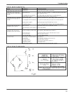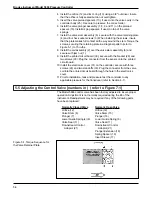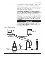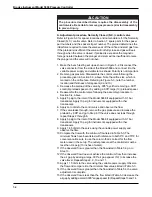
5-13
Troubleshooting
·
For a downstream controller P1 is the reference pressure. P2 is the
calibration pressure.
P1=P
Ref
P2=P
Cal
3. Determine the C
v
for the application. The ratio between P1 and P2 will
determine the calculation to use:
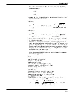
Equation #1
P2
Q
max
SG * T
If:
>
0.5 use: C
v
=
P1
800,000
(P1-P2) * P2
Equation #2
P2
Q
max
If:
<
0.5 use: C
v
=
SG * T
P1
397,000 * P1
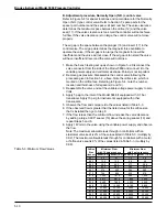
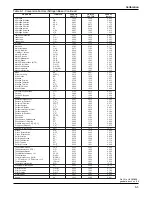
4. Select the orifice size from Table 5-4 that has a C
v
just greater than the
C
v
determined in Step 3.
5. Check to see if the maximum operating pressure drop is greater than
the maximum allowable pressure drop for the orifice size selected. If the
pressure drop is too high for the orifice selected the instrument will not
be able to function correctly. This situation can be corrected by reducing
the pressure drop to the allowable level, or, reducing the maximum flow
so a smaller orifice will be selected.
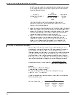
An example Model 5866 application is shown in Figure 5-6 to illustrate
the orifice sizing procedure.
Given:
Controller Type: Upstream
Gas: 5/8 Nitrogen, 3/8 Hydrogen
Temperature; 70°F (530°R)
Maximum Flow: 800 sccm
Calibration Pressure: 100 psig (114.7 psia)
Reference Pressure; 1 atmosphere (14.7 psia)
Max Flow: 10 slpm (0°C ref. temp.)
Calculations:
SG Mixture = (3/8 x 0.070) + (5/8 x 0.964) = .629
Minimum Pressure Drop = 114.7 x .05 = 5.7 psi
Maximum Pressure Drop = 114.7 - 14.7 = 100 psi
P1 = 14.7 + 5.7 = 20.4 psia
P2 = 14.7 psia
P2/P1 = 14.7/20.4 = 0.721 which is > 0.5 therefore use equation #1
800
0.629 x 530
C
v
=
=
2.0 x 10
-3
800,000
(20.4 - 14.7) x 14.7
Summary of Contents for 5866
Page 20: ...3 3 Operation Figure 3 2 Proportional Control Figure 3 3 Integral Control ...
Page 21: ...Brooks Instrument Model 5866 Pressure Controller 3 4 Figure 3 4 P I Control ...
Page 23: ...Brooks Instrument Model 5866 Pressure Controller 4 2 ...
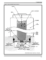
Page 32: ...5 9 Troubleshooting Figure 5 3 Valve Adjusting Spacer Locations ...
Page 34: ...5 11 Troubleshooting Figure 5 4 Valve Adjusting Spacer Locations Normally Open N O Valve ...
Page 43: ...Brooks Instrument Model 5866 Pressure Controller 6 6 ...
Page 45: ...Brooks Instrument Model 5866 Pressure Controller 7 2 Figure 7 1 Model 5866E Parts Drawing ...
Page 47: ...Brooks Instrument Model 5866 Pressure Controller 7 4 Figure 7 2 Model 5866M Parts Drawing ...
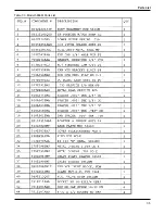
Page 48: ...7 5 Parts List Table 7 3 Model 5866M Parts List ...
Page 49: ...Brooks Instrument Model 5866 Pressure Controller 7 6 ...
Page 65: ......


