Bronkhorst®
Instruction Manual IQ+FLOW® Series Digital Mass Flow / Pressure Controllers for Gases
9.17.045V
27
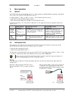
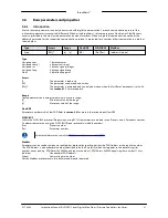
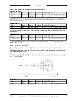
Dynamic Display Factor
Type
Access
Range
FlowDDE
FLOW-BUS
Modbus
Float
RW
0…1.0
56
117/1
0xF508…0xF509/62729…62730
This value should not be changed.
Static Display Factor
Type
Access
Range
FlowDDE
FLOW-BUS
Modbus
Float
RW
0…1.0
57
117/2
0xF510…0xF511/62737…62738
This value should not be changed.
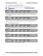
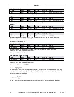
CycleTime
Type
Access
Range
FlowDDE
FLOW-BUS
Modbus
Unsigned char
R
0…255
52
114/12
0x0E4C/3661
Note: The unit of parameter CycleTime is 10 ms. Example: value 0.2 means 2 ms
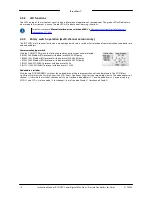
4.1.6
Alarm / Status parameters
See
Operation Instructions Digital Instruments (document no 9.17.023)
4.1.7
Counter parameters
See
Operation Instructions Digital Instruments (document no 9.17.023)
4.2
Special instrument features
4.2.1
Auto zeroing
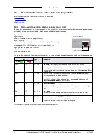
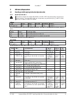
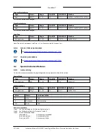
To start the auto zero-procedure by digital operation two parameters should be written:
Control Mode
Type
Access
Range
FlowDDE
FLOW-BUS
Modbus
Unsigned char
RW
0…255
12
1/4
0x0024/37
Calibration Mode
Type
Access
Range
FlowDDE
FLOW-BUS
Modbus
Unsigned char
RW
0…255
58
115/1
0x0E61/3682
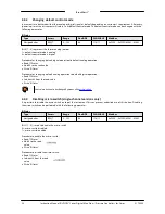
Value
Mode
Instrument action
0
Idle
Idle
9
Auto zero
Auto-zeroing
255
Error
Idle
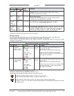
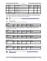
Auto-zero procedure:
Step 1: Set 'Control Mode' to 'Calibration Mode' (value 9)
Step 2: Set 'Calibration Mode' to 'Auto zero' (value 9)
Step 3: Check 'Calibration Mode',
Idle (value 0)
Auto-zeroing succeeded
Auto zero (value 9)
Auto-zeroing active
Error (value 255)
Auto-zeroing failed

