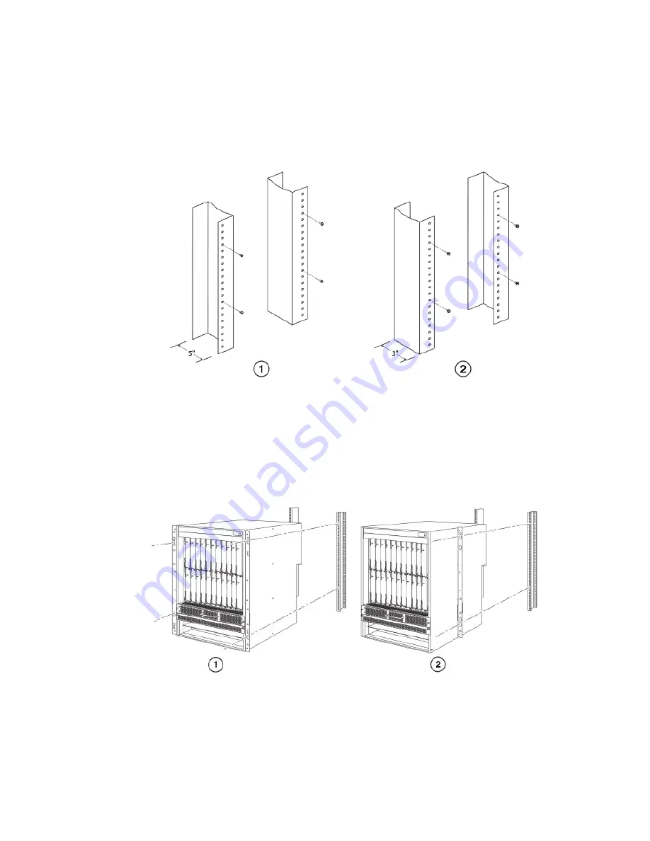
2. Position four mounting screws for each router using the spacing of the keyhole slots (the ones with the narrow portion pointing
up) on the mounting brackets as a guide, as shown in the following figure. When tightening the mounting screws, leave
approximately 1/4 inch of clearance between the back of the screw head and the rack posts.
FIGURE 40
Positioning the mounting screws in the rack posts
1.
Unequal flange equipment rack
2.
Network equipment rack
3. Starting with the router that will be in the lowest position in the rack, mount the router in the rack as shown in the following figure.
With two or more people lifting the router, slip the wide portion of each keyhole slot over the corresponding mounting screw in
the rack post.
FIGURE 41
Mounting the Brocade MLXe Series-16 router in a rack
1.
Front-mount configuration
2.
Mid-mount configuration
4. Slide the router down so that the mounting screw heads are in the narrow portion of the keyhole slots.
Installing a Brocade MLXe Series-16 router
Brocade NetIron MLXe Series Hardware Installation Guide
114
53-1004203-04
Summary of Contents for NetIron MLXe Series
Page 8: ...Brocade NetIron MLXe Series Hardware Installation Guide 8 53 1004203 04...
Page 12: ...Brocade NetIron MLXe Series Hardware Installation Guide 12 53 1004203 04...
Page 20: ...Brocade NetIron MLXe Series Hardware Installation Guide 20 53 1004203 04...
Page 192: ...Brocade NetIron MLXe Series Hardware Installation Guide 192 53 1004203 04...
Page 270: ...Brocade NetIron MLXe Series Hardware Installation Guide 270 53 1004203 04...
Page 286: ...Brocade NetIron MLXe Series Hardware Installation Guide 286 53 1004203 04...
Page 292: ...Brocade NetIron MLXe Series Hardware Installation Guide 292 53 1004203 04...


