background image

Mounting the access point

2

Brocade Mobility 7131 Series Access Point Installation Guide

13

53-1001935-02

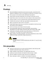
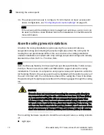
CAUTION

Ensure you are placing the antennas on the correct connectors 
(depending on your single or dual-radio model and frequency used) to 
ensure the successful operation of the access point.

NOTE

It is recommended the access point be mounted with the RJ45 cable connector 
oriented upwards or downwards to ensure proper operation.

11. Cable the Mobility 7131 Series Access Point using either the Power over 

Ethernet (PoE) or an approved line cord and power supply.

For POE installations, connect an RJ-45 CAT5e (or CAT6) Ethernet cable 
between a PoE switch port and the Brocade Mobility 7131 GE1/POE port.

For standard power adapter and line cord installations:

a. Connect a RJ-45 CAT5e (or CAT6) Ethernet cable between the network data 

supply (host) and the Mobility 7131 Series Access Point GE1/POE or GE2 
port.

b. Verify the power adapter is correctly rated according the country of 

operation.

c. Connect the power supply line cord to the power adapter.

d. Attach the power adapter cable into the power connector on the Mobility 

7131 Series Access Point .

e. Attach the power supply line cord to a power supply.

CAUTION

Do not actually connect to the power source until the cabling portion of 
the installation is complete.

12. Verify the behavior of the access point LEDs. For more information, see 

“LED 

indicators”

 on page 19.

13. The access point is ready to configure. For information on basic access point 

device configuration, see 

“Configuring basic device settings”

 on page 29.

Summary of Contents for Mobility 7131 Series

Page 1: ...Brocade Mobility 7131 Series Access Point Installation Guide Supporting software release 4 1 0 0 and later 53 1001935 02 Rev B...

Page 2: ...nications Systems Inc shall have no liability or responsibility to any person or entity with respect to any loss cost liability or damages arising from the information contained in this book or the co...

Page 3: ...22 Single radio 2 4 Ghz LEDs 23 Single radio 5 Ghz LEDs 24 Rear LED 25 3 Basic Mobility 7131 Series Configuration 27 Resetting the access point s password 29 Configuring basic device settings 29 Confi...

Page 4: ...sure use properly 48 Remote and standalone antenna configurations 49 Power supply 49 Wireless devices countries 49 Country selection 49 Operation in the US 49 Radio frequency interference requirements...

Page 5: ...orking knowledge of Layer 2 and Layer 3 switching and routing If you are using a Brocade Layer 3 Controller you should be familiar with the following protocols if applicable to your network IP RIP OSP...

Page 6: ...emphasizes important information or provides a reference to related information CAUTION A Caution statement alerts you to situations that can be potentially hazardous to you or cause damage to hardwa...

Page 7: ...e accuracy and completeness of this document However if you find an error or an omission or you think that a topic needs further development we want to hear from you Forward your feedback to documenta...

Page 8: ...r remote site All traffic between the adaptive access points and the wireless switch is secured though an IPSec tunnel Additionally compatibility with Brocade s RF Management Suite RFMS allows you to...

Page 9: ...f the equipment Do not work with power circuits in dimly lit spaces Do not install this equipment or work with its power circuits during thunderstorms or other weather conditions that could cause a po...

Page 10: ...obility 7131 Series Access Point Installation Guide 3 53 1001935 02 Identify and prepare Ethernet and console port connections Verify that cable lengths are within the maximum allowable distances for...

Page 11: ...Site preparation 1 4 Brocade Mobility 7131 Series Access Point Installation Guide 53 1001935 02...

Page 12: ...Brocade Mobility 7131N Access Point verify the following Do not install in wet or dusty areas without additional protection Contact a Brocade representative for more information Verify the environment...

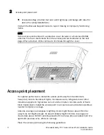
Page 13: ...the cover Access point placement For optimal performance install the access point away from transformers heavy duty motors fluorescent lights microwave ovens refrigerators and other industrial equipm...

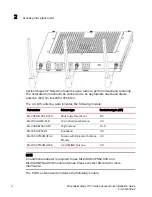
Page 14: ...nded operational environment of your access point The Brocade Mobility 7131N Access Point can be purchased in a three radio configuration If a three radio SKU is purchased the access point ships with...

Page 15: ...following models NOTE An additional adapter is required to use ML 2499 11PNA2 01R and ML 2499 BYGA2 01R model antennas Please contact Brocade for more information The 5 GHz antenna suite includes the...

Page 16: ...ions Choose one of the following mounting options based on the physical environment of the coverage area Do not mount the access point in a location that has not been approved in a site survey Wall mo...

Page 17: ...required to install the access point on a wall consists of Two Phillips pan head self tapping screws ANSI Standard 6 18 X 0 875in Type A or AB Self Tapping screw or ANSI Standard Metric M3 5 X 0 6 X 2...

Page 18: ...Mounting the access point 2 Brocade Mobility 7131 Series Access Point Installation Guide 11 53 1001935 02...

Page 19: ...vertical centerline of the template needs to be positioned horizontally The cabling shall exit the access point in a horizontal direction 3 At mounting targets A and B mark the mounting surface throu...

Page 20: ...ility 7131 GE1 POE port For standard power adapter and line cord installations a Connect a RJ 45 CAT5e or CAT6 Ethernet cable between the network data supply host and the Mobility 7131 Series Access P...

Page 21: ...d attach a security cable to the access point lock port 3 Attach the antennas to their correct connectors For information on the antennas available to the access point see Antenna options on page 7 CA...

Page 22: ...n of the installation is complete 5 Verify the behavior of the access point LEDs For more information see LED indicators on page 19 6 Align the bottom of the ceiling T bar with the back of the access...

Page 23: ...ocade Mobility 7131 Access Point and Brocade Mobility 7131N Access Point are Plenum rated to UL2043 and NEC1999 to support above the ceiling installations To ensure UL compliance and proper access poi...

Page 24: ...d place it aside 2 If required install a safety wire between 1 5mm 06in and 2 5mm 10in in diameter in the ceiling space 3 If required install and attach a security cable to the access point s lock por...

Page 25: ...see Antenna options on page 7 CAUTION Ensure you are placing the antennas on the correct connectors depending on your single or dual radio model and frequency used to ensure the successful operation o...

Page 26: ...ling portion of the installation is complete 15 Verify the behavior of the access point LED light pipe For more information see LED indicators on page 19 16 Place the ceiling tile back in its frame an...

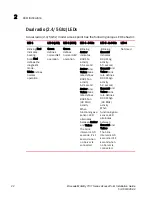
Page 27: ...LEDs feed each light pipe the pattern is from left to right then right to left NOTE The LED blink rate is proportional to activity The busiest traffic corresponds to the fastest blink while the slowe...

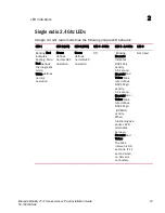
Page 28: ...MHz activity When functioning as a sensor LED alternates between Amber and Yellow The blink interval is 0 5 seconds It s 1 second when no Server is connected Blinking Emerald indicates 802 11bg activ...

Page 29: ...ates 802 11a activity A 5 second Amber and Yellow blink rate defines 802 11an activity A 2 second Amber and Yellow blink rate defines 802 11an 40 MHz activity When functioning as a sensor LED alternat...

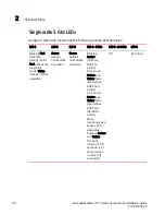
Page 30: ...Red defines the diagnostic mode White defines normal operation Green defines normal GE1 operation Green defines normal GE2 operation Off Blinking Emerald indicates 802 11bg activity A 5 second Emeral...

Page 31: ...Red defines the diagnostic mode White defines normal operation Green defines normal GE1 operation Green defines normal GE2 operation Blinking Amber indicates 802 11a activity A 5 second Amber and Yel...

Page 32: ...ess point is optionally viewed using a single customer installed extended light pipe adjusted as required to suit above the ceiling installations The LED light pipe has the following color display and...

Page 33: ...LED indicators 2 26 Brocade Mobility 7131 Series Access Point Installation Guide 53 1001935 02...

Page 34: ...optimal viewing of the Web UI the screen resolution should be set to 1024 x 768 pixels or greater NOTE For advanced configuration options beyond the scope of this guide refer to the Brocade Mobility 7...

Page 35: ...7131 Series Access Point Installation Guide 53 1001935 02 The login screen displays 1 Log in using admin as the default User ID and admin123 as the default password If the default login is successful...

Page 36: ...word to its default value Doing so also reverts the access point s security radio and power management configuration to their default settings Only an installation professional should reset the access...

Page 37: ...and are described within this section To define a basic access point configuration 1 Select System Configuration Quick Setup from the menu tree if the Quick Setup screen is not already displayed 2 Se...

Page 38: ...operation Selecting the correct country is central to legally operating the access point Each country has its own regulatory restrictions concerning electromagnetic emissions and the maximum RF signal...

Page 39: ...s radio s Remember the options available depend on the single dual or three radio model SKU deployed NOTE If using a three radio model AP 7131N Access Point the radio three configuration option could...

Page 40: ...GHz WLAN only no Sensor Not Available Radio 1 WLAN Radio 2 WLAN Radio 1 WLAN Radio 2 WLAN Radio 3 Disabled Sensor only Spectrum Analysis mode no WLAN Radio 1 WIPS Radio 1 WIPS Radio 2 WIPS Radio 1 WIP...

Page 41: ...ets b Select the This Interface is a DHCP Client checkbox to enable DHCP for the access point WAN connection This is useful if the target corporate network or Internet Service Provider ISP uses DHCP D...

Page 42: ...data networks h Select the Keep Alive checkbox to enable occasional communications over the WAN port even when client communications to the WAN are idle Some ISPs terminate inactive connections while...

Page 43: ...fy routing and data transmission e If using the static or DHCP Server option enter a Default Gateway to define the numerical IP address of a router the access point uses on the Ethernet as its default...

Page 44: ...acon Settings those fields can also be defined at this time Define the Channel Settings Power Level and 802 11 mode in respect to the 2 4 or 5 GHz 802 11b g n or 802 11a n radio traffic and anticipate...

Page 45: ...uide available at http www brocade com support To configure WEP 128 1 From the Quick Setup screen click the Create button to the right of the Security Policy item The New Security Policy screen displa...

Page 46: ...teroperability Pass Key Specify a 4 to 32 character pass key and click the Generate button The access point other proprietary routers and Motorola clients use the same algorithm to convert an ASCII st...

Page 47: ...vity using WNMP To ping a specific client to assess its connection with an access point NOTE Before testing for connectivity the target client needs to be set to the same ESSID as the access point Sin...

Page 48: ...ty 7131 Series Access Point Product Reference Guide available at http www brocade com support Refer to Chapter 4 to define System Settings beyond the scope of the Quick Setup screen configure access p...

Page 49: ...Where to go from here 3 42 Brocade Mobility 7131 Series Access Point Installation Guide 53 1001935 02...

Page 50: ...1 10 in Height 14 cm Depth x 20 32 cm Width x 2 79 cm Height Housing Metal plenum rated housing UL2043 Weight 2 22 lbs Operating Temperature 4 F to 122 F 20 C to 50 C Storage Temperature 40 F to 158 F...

Page 51: ...8VDC 0 75A Operating Channels All channels from 4920 MHz to 5825 MHz except channel 52 64 Channels 1 13 EU Channels 1 11 US Canada Channel 14 2484 MHz Japan only Actual operating frequencies depend on...

Page 52: ...2 5 5 11 6 9 12 18 24 36 48 and 54Mbps 802 11a 6 9 12 18 24 36 48 and 54Mbps 802 11n MCS 0 15 up to 300Mbps Wireless Medium Direct Sequence Spread Spectrum DSSS Orthogonal Frequency Division Multiple...

Page 53: ...02 Brocade Mobility 7131 Series Access Point console cable A console cable pictured below is used to connect the Brocade Mobility 7131 Series Access Port s serial port to an RS 232 DB 9 serial port o...

Page 54: ...Unauthorized antennas modifications or attachments could cause damage and may violate regulations Country approvals Regulatory markings are applied to the device signifying the radio s are approved f...

Page 55: ...ants etc and areas where the air contains chemicals or particles such as grain dust or metal powders Safety in hospitals Wireless devices transmit radio frequency energy and may affect medical electri...

Page 56: ...Listed to UL CSA 60950 1 and certified to IEC60950 1 and EN60950 1 with SELV outputs Use only a Brocade approved power supply Use of alternative power supply will invalidate any approval given to this...

Page 57: ...the user is encouraged to try to correct the interference by one or more of the following measures Reorient or relocate the receiving antenna Increase the separation between the equipment and receiver...

Page 58: ...ne and two Antennas not included in this list or having a gain greater than 13 9 dBi 2 4 GHz and 13 dBi 5 GHz for radios one and two are prohibited for use with this device This device has been design...

Page 59: ...ITE This is a Class B product based on the standard of the Voluntary Control Council for Interference from Information Technology Equipment VCCI If this is used near a radio or television receiver in...

Page 60: ...uipamento opera em car ter secund rio isto n o tem direito a prote o contra interfer ncia prejudicial mesmo de esta es do mesmo tipo e n o pode causar interfer ncia a sistemas operando em car ter prim...

Page 61: ...If found the user shall cease operating immediately until no interference is achieved The said legal communications means radio communications is operated in compliance with the Telecommunications Ac...

Page 62: ...following two expression should be displayed 1 This radio equipment can be interfered during operation 2 This radio equipment cannot provide a service relevant to the human life safety South Korea S K...

Page 63: ...stallation Guide 56 53 1001935 02 Chapter 6 Waste Electrical and Electronic Equipment WEEE For information on WEEE please go to http www brocade com sites dotcom company corporate responsibility corpo...

Page 64: ......

Reviews: