Specifications subject to change without notice. © 2013 Brivis Climate Systems Pty Ltd
19
6.7 Oil Checking and Top Up
•
The compressor is charged with PVE (polyvinyl-ether) lubricant
•
For pipe work up to 15m equivalent length and in installations with good oil return, no additional oil is required
•
If pipe lines exceed 15m, then additional oil is needed. Add 1% – 2 % of total refrigerant charge (in weight) to top
up the oil.
•
Top up while the compressor is idle. Use suitable oil pump via the access port on the compressor suction line
7.0 Start-Up and Commissioning
•
Ensure that a Return Air Filter is fitted prior to fan start up
•
Measure and record the system details as noted under PRELIMINARY SYSTEM INFORMATION and check all
items as noted under PRE START-UP on the Commissioning Sheet provided
•
Switch the unit on in cooling mode with the thermostat set to minimum temperature set point
•
Measure and record all items as noted under OPERATION CHARACTERISTICS on the Commissioning Sheet
provided
•
Check suction and liquid pressures
•
Care must be taken to charge the system correctly. Undercharge will result in lack of capacity and the unit may
lock out on its LP (Low Pressure) safety switch. Overcharge will result in high head pressures whilst unit is
operating
•
Measure the compressor suction pressure and convert to a compressor saturated suction temperature (CSST)
using R410a refrigerant pressure/temperature table
•
Measure the suction line temperature (SLT) approximately 100mm before the compressor
•
Calculate the superheat (SH) = SLT – CSST
•
Measure the compressor discharge pressure and convert to a condensing temperature (CT) using R410a
refrigerant pressure / temperature table
•
Measure the liquid line temperature (LLT) between the outdoor coil and indoor unit throttling device in cooling
mode
•
Calculate the sub-cooling (SC) = CT – LLT
•
Measure the outdoor ambient air temperature
•
Measure the indoor return and supply air dry bulb temperatures, both before and after the indoor coil
•
Measure the indoor air quantity ensuring it falls within the indoor coil’s limits
•
Adjust the fan speed to suit the static pressure and air quantity requirements
•
Allow system pressure to stabilise for a minimum of 20 minutes
•
Instruct the customer on system capability and correct operation
•
Please ask the customer to fill in the CUSTOMER DETAILS section and to register their product warranty with
Brivis
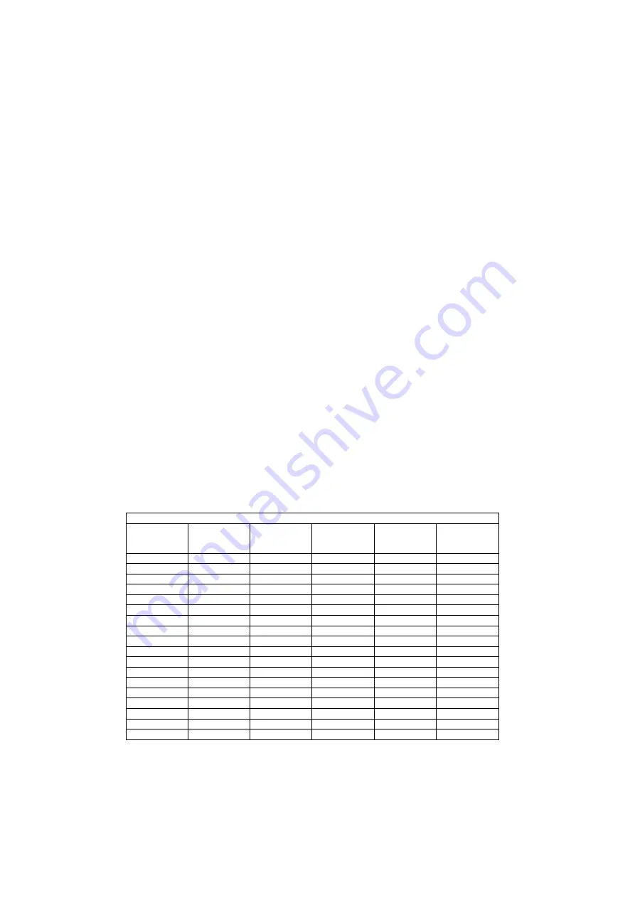
R410a Pressure-Temperature chart
Saturated
Temperature
°C
Gauge
Pressure
kPa
Saturated
Temperature
°C
Gauge
Pressure
kPa
Saturated
Temperature
°C
Gauge
Pressure
kPa
-40
79
-4
602
32
1866
-38
95
-2
648
34
1968
-36
113
0
697
36
2073
-34
132
2
749
38
2183
-32
152
4
803
40
2297
-30
174
6
859
42
2415
-28
196
8
918
44
2537
-26
221
10
980
46
2664
-24
246
12
1045
48
2796
-22
274
14
1113
50
2932
-20
303
16
1183
52
3073
-18
334
18
1257
54
3219
-16
366
20
1334
56
3371
-14
400
22
1414
58
3527
-12
436
24
1497
60
3689
-10
475
26
1584
62
3857
-8
515
28
1674
64
4031
-6
557
30
1768
66
4210
Table 4 – Saturated Pressure-Temperature R410a
FAILURE TO COMPLETE PROPER START UP AND COMMISSIONING MAY VOID BRIVIS PRODUCT WARRANY


