998rev401
5K821
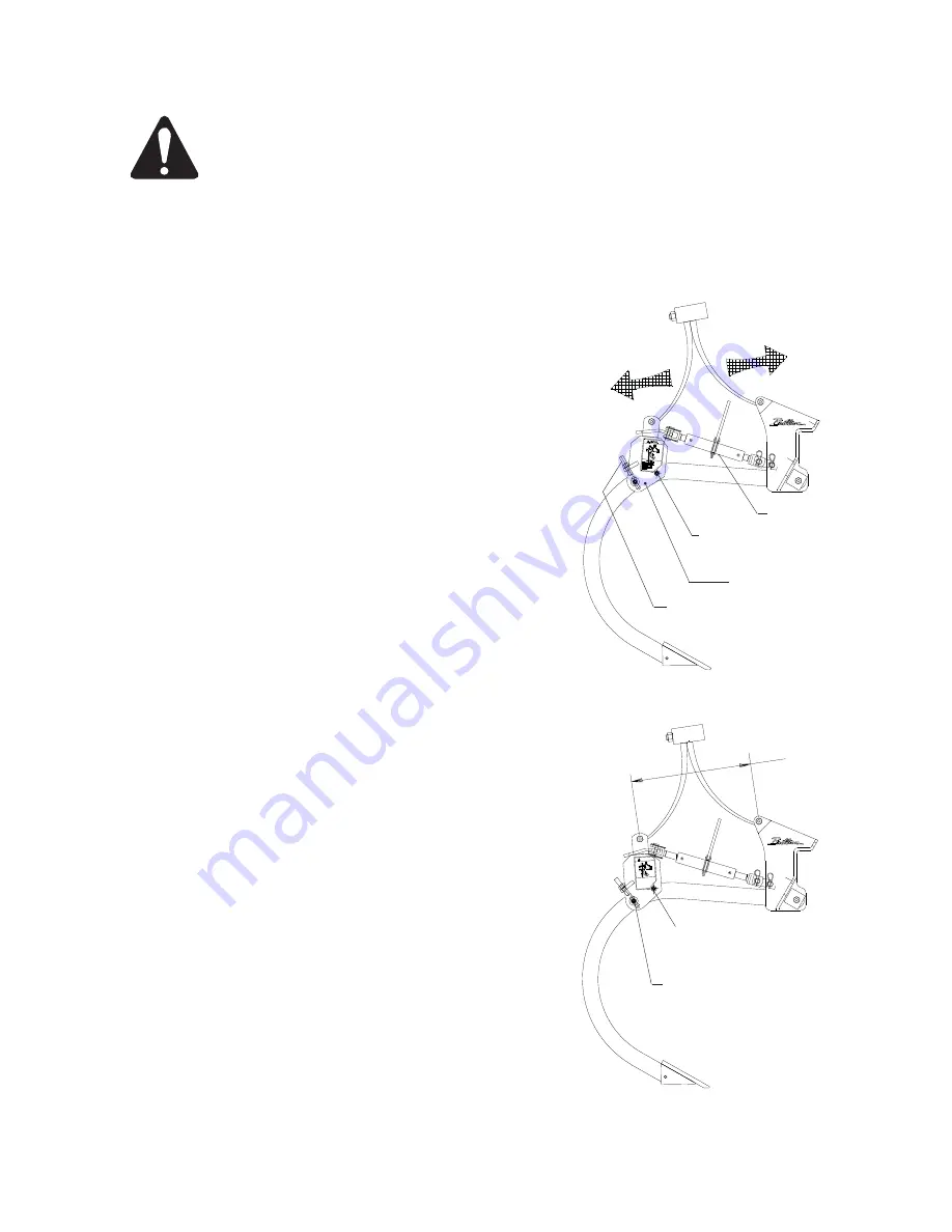
SERVICE TOOL
REAR BRACKET
BOLT TO BE REMOVED
PIVOT BOLT
(5/8” X 4” CAPSCREW,
FLAT WASHERS, & LOCK NUT)
DIAGRAM A
DIAGRAM B
5/8” x 3 1/4” CAPSCREW,
LOCKWASHER, &HEX NUT
3/4” SET SCREW
(or Carriage Bolt)
& 3/4” HEX NUT
21 1/16”
Service of Preloaded Shank Assembly
SPRING IS UNDER LOAD
Do not disassemble without use of service tool and following the procedure.
Spring is loaded and improper removal of bolts could result in serious injury.
Refer to Repair Parts Catalog for additional help in identifying parts of shank assembly and service kit.
SERVICE INSTRUCTIONS
1.
Install
service tool
as shown in Diagram A.
Plate slides through the back of the rear
bracket. Pin the lug to the hole in the
front bracket casting and secure pins with
hairpin cotters.
2.
Loosen 3/4” hex nut and carriage bolt. Slightly
loosen both bottom bolts of rear bracket.
3.
Retract the ratchet assembly of the service
tool to transfer the force of the spring to
the service tool. Continue until the bolt
to be removed, as shown in Diagram B, is loose
and can be removed.
4.
Remove bolt shown in Diagram B and extend the
ratchet assembly of the service tool until
the spring is relaxed.
5.
Service parts as needed.
PRELOAD INSTRUCTIONS
1.
Install
service tool
as shown in Diagram B.
Plate slides through the back of the rear
bracket. Pin the lug to the hole in the
front bracket casting and secure pins with
hairpin cotters.
2.
Retract the ratchet assembly of the service
tool to pivot the rear bracket about the pivot
bolt shown in Diagram B. Retract the assembly
until the 21 1/16” dimension between spring
mount centers is achieved.
3.
Tighten carriage bolt firmly against shank and lock
in place with 3/4” hex nut.
Tighten remaining bolts at this time.
4.
Install the bolt that had been removed for service.
5.
Extend the ratchet assembly of the service tool
until it is relaxed.
Remove the service tool.
Page 13
Summary of Contents for Landcommander II LCS11152
Page 2: ...998rev401 5K821...
Page 4: ...998rev401 5K821...
Page 42: ...998rev401 5K821 30 30 0 LCS330 Figure 30a Page 36...
Page 43: ...998rev401 5K821 24 24 48 0 48 Figure 30b LCS524 Page 37...
Page 44: ...998rev401 5K821 30 60 0 60 30 Figure 30c LCS530 Page 38...
Page 45: ...998rev401 5K821 Page 38A Figure 30c 1 LCS720 40 0 40 60 20 20 60...
Page 46: ...998rev401 5K821 Page 38B This page left blank intentionally...
Page 47: ...998rev401 5K821 Figure 30d LCS915 Page 39 0 60 30 30 60 45 15 15 45...
Page 48: ...998rev401 5K821 Figure 30e LCS724 Page 40 48 0 48 72 24 24 72...
Page 49: ...998rev401 5K821 60 0 60 90 30 30 90 Figure 30f LCS730 Page 41...
Page 50: ...998rev401 5K821 72 72 24 24 96 48 0 48 96 Figure 30g LCS924 Page 42...
Page 51: ...998rev401 5K821 60 30 0 30 60 75 45 15 15 45 75 Figure 30h LCS1115 Page 43...
Page 52: ...998rev401 5K821 90 60 30 0 30 60 90 75 45 15 15 45 75 Figure 30i LCS1315 Page 44...
Page 60: ...998rev401 5K821...
Page 61: ......


