14
BRIGGSandSTRATTON.COM
Inspect Muffler and Spark Arrester
Inspect the muffler for cracks, corrosion, or other damage.
Remove the spark arrester, if equipped, and inspect for
damage or carbon blockage.
WARNING
Exhaust heat/gases could ignite combustibles
or structures resulting in death, serious
injury and/or property damage.
Contact with muffler area could cause
burns resulting in serious injury.
• DO NOT touch hot parts and AVOID hot exhaust gases.
• Allow equipment to cool before touching.
• DO NOT install the generator closer than 5 feet (1.5m)
from any combustibles or structures with combustible
walls having a fire resistance rating of less than 1 hour.
• Keep at least minimum distances shown in
General
Location Guidelines
to insure for proper generator cooling
and maintenance clearances.
• It is a violation of California Public Resource Code,
Section 4442, to use or operate the engine on any forest-
covered, brush-covered, or grass-covered land unless
the exhaust system is equipped with a spark arrester, as
defined in Section 4442, maintained in effective working
order. Other states or federal jurisdictions may have
similar laws.
Contact the original equipment manufacturer, retailer, or
dealer to obtain a spark arrester designed for the exhaust
system installed on this engine.
• Replacement parts must be the same and installed in the
same position as the original parts.
Clean and inspect the spark arrester as follows:
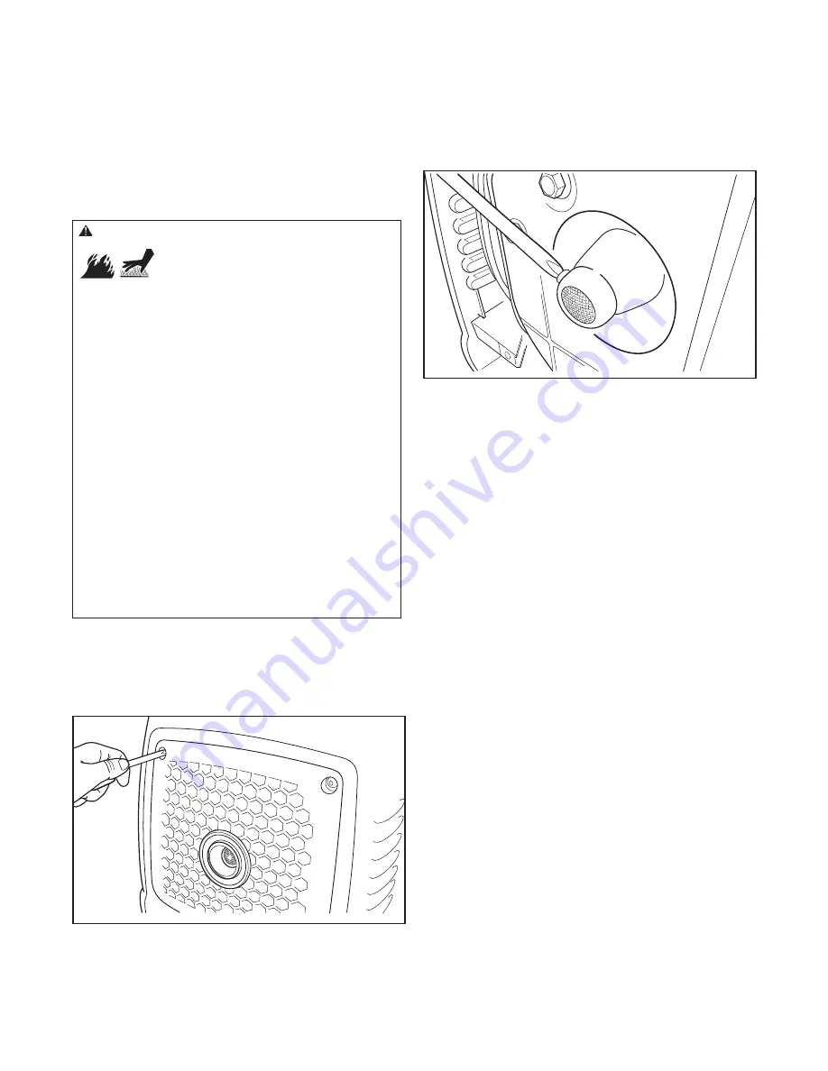
1. To remove muffler guard, remove four screws that
connects guard to generator (Figure 11).
Figure 12
Figure 11
2. Remove screw (Figure 12) that attaches spark arrester
screen muffler. Remove spark arrester screen.
3. Inspect screen and obtain a replacement if torn,
perforated, or otherwise damaged. DO NOT use a
defective screen. If screen is not damaged, clean it with
a brush.
4. Reattach screen to muffler. Reattach muffler guard.
Adjust Valve Clearance
NOTE:
Check valve clearance while the engine is cold.
1. Turn crankshaft counterclockwise until piston is at top
dead center on the compression stroke. This prevents
the compression release from holding the valves open.
2. Insert a narrow screwdriver or rod into the spark plug as a
gauge, then slowly turn crankshaft counterclockwise until
the piston has moved down the bore by 1/4” (6 mm).
3. Using feeler gauge, check valve clearance. Clearance
should be as listed in Specifications.
4. If not, adjust jam nut until correct clearance is obtained.
Not
for
Reproduction


