


75
Share
: Share/do not share options are available for user selection. If share option is selected, then
Observer data available in the computer can be shared from other computers. On selection of this share
data, shared folder will be created in C:\Observer.
For example, you have one recorder and wish to analyze historical data at different computer. While
opening project in the second computer, directly link to the project file available under C:\Observer
through network configuration. This will minimize the data transfer between recorder and the computers
and make it more efficient by using available resources through network configurations.
: The default Port number 25 is used to send email from STMP server. If your network
administrator configured different port in your LAN for accessing internet/email, then you have to modify
the port number accordingly.
To send an email for any event, the procedure is as follows.
Set SMTP server details as below. Please contact system or network administrator for the server details if
your computer is connected in LAN.
Host, Port, User name, From: Sender email address
To: Receiver email address (Max.10 email addresses can be selected)
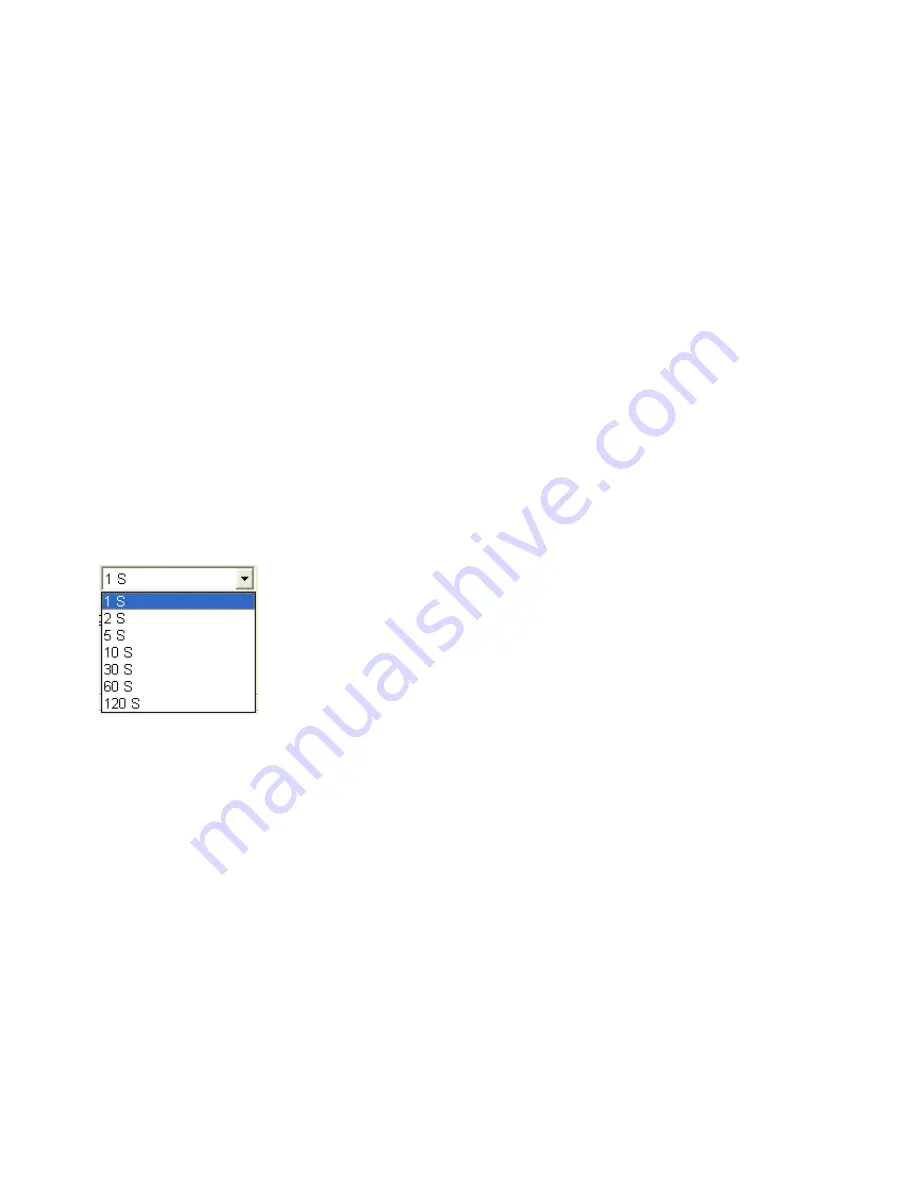
Communication
: It is used to set data display time for Real-Time Viewer. User can select one from the
following for real time monitoring.
For example, if recorder and Observer are located at different places connected through Ethernet across
different gateways, then user can set the communication time from this option. If 60 sec is set, then
Observer will exchange data with the recorder once in 60 sec. When recorder and Observer are separated
in far distance, it is preferable to use Ethernet option so that it can have better data transfer rate for
communication.
Summary of Contents for VR06
Page 1: ...User Manual Paperless Recorder VR06 UMVR061D Brainchild Electronic Co Ltd 4th Edition 10 2013 ...
Page 17: ...17 Figure 2 6 Figure 2 7 Figure 2 8 ...
Page 19: ...19 Figure 2 10 Figure 2 11 ...
Page 25: ...25 Digital input card DI181 Figure 2 21 Analog output card AO183I AO183V Figure 2 22 ...
Page 27: ...27 Figure 2 25 Figure 2 26 ...
Page 69: ...69 Make sure that RS 232 communication setting at the recorder and PC are equal ...
Page 86: ...86 7 Trouble shooting ...
Page 87: ...87 ...
Page 88: ...88 ...


