background image

35

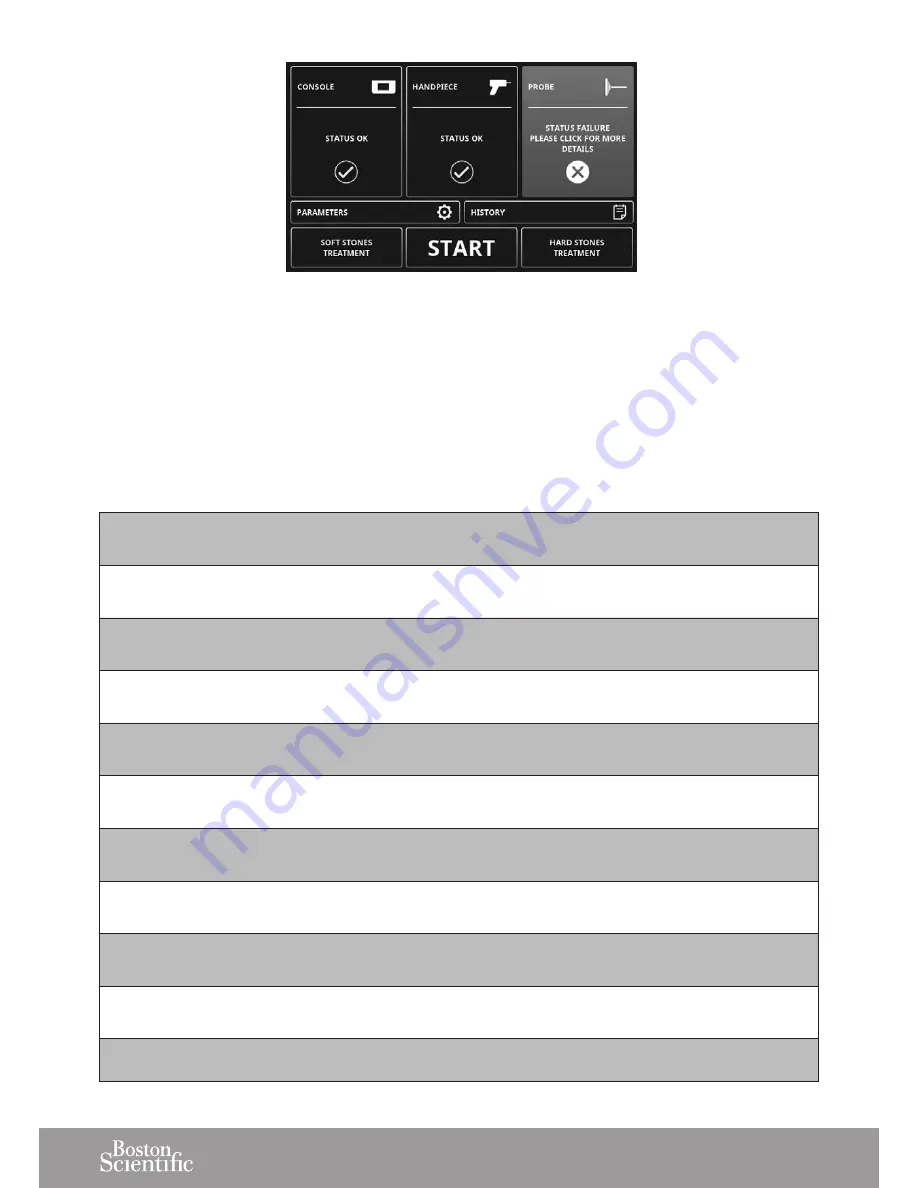
Figure 83

1.  Press the highlighted faulty component and follow 

the interactive menu to identify the exact origin of 

the error. 

2.  Follow the recommended action that is displayed.

3.  If the solutions proposed fail to solve the problem, 

please contact your local Boston Scientific sales repre-

sentatives. Do not, in any case, return a product before 

troubleshooting of the error has been performed.

4.  The following table provides more detailed information 

about failures: error number and associated error 

messages.

• 

Console

E001 - The cooling pump is not detected and handpiece cooling might not be available. Please restart device. 

Please contact your service center if the error persists.

E002 - The cooling valve is not detected and handpiece cooling might not be available. Please restart device. 

Please contact your service center if the error persists.

E008 - Configuration files of the console are corrupted and informations might be incorrect. Please contact your 

service center.

E009 - Console internal communication error. Please restart device. Please contact your service center if the 

error persists.

E010 - Pedal not detected. Please verify that the connector of the pedal is connected to the console. Please 

contact your service center if the error persists.

E016 - No suction system has been detected. Please restart device or contact your service center if the error 

persists.

E017 - Two suction systems seem to be connected. Please restart device or contact your service center if the 

problem persists.

E018 - The console temperature is high. Treatment is still possible but verify the console is placed in a correctly 

ventilated place

E019 - The console temperature is too high. System needs to cool down. Please keep it powered while temperature 

returns to safe level.

E020 - Console internal communication error. System trying to recover. Please restart device or contact your 

service center if the error persists.

E024 - Console internal communication error. Please restart device or contact your service center if the error persists.

Summary of Contents for Swiss LithoCast Trilogy FT-235

Page 1: ...INSTRUCTIONS FOR USE Caution Federal USA law restricts this device to sale by or on the order of a physician ...

Page 2: ...2 ...

Page 3: ...ints Intended Use The product is intended for the fragmentation and removal of urinary tract calculi in the kidney ureter and bladder Operating mode The product can deliver ultrasound and ballistic energies through a single probe simultaneously or separately to fragment stones The product can extract stone fragments through the probe while delivering energy or without delivering energy The product...

Page 4: ...OCEDURE 23 6 1 COMPLETING TREATMENT 23 6 2 DISCONNECTING THE HANDPIECE 24 6 3 RECORDING TREATMENT DATA 25 6 4 DISCONNECTING THE STONE CATCHER 26 6 5 ELIMINATING THE STONE CATCHER CONTENTS 26 6 6 CONSERVING THE STONE CATCHER CONTENTS 26 6 7 DISPOSING OF SINGLE USE COMPONENTS 26 6 8 SWITCHING OFF THE CONSOLE 26 7 CLEANING DISINFECTING AND STERILIZING 27 7 1 MULTIUSE COMPONENTS 27 7 2 CONSOLE PEDAL A...

Page 5: ... aspiration connector and re usable wrenches are sterilized before proceeding with installation To avoid the risk of electric shock this product must only be connected to a mains power supply with protective earth No modification shall be made on this product The mains power switch of the product must be accessible at any time For sterilization the handpiece must have the lumen positionned vertica...

Page 6: ...E REF DESIGNATION QTY 1 Console with peristaltic pump or 1 2 Cart optional 1 3 Fluid management system optional 1 4 USB key 1 5 2 5 L Demineralized water 1 6 Stone catcher support 1 7 Cooling system filling kit 1 8 Power cord 1 9 Wired pedal 1 10 Draining tube 1 11 External video cord optional 1 12 Cleaning brush 1 13 Cleaning rod 1 Figure 1 ...

Page 7: ...d before use 19 Handpiece 1 To be sterilized before use Figure 2 1 2 4 3 5 6 8 7 11 9 10 13 12 REF DESIGNATION TO BE USED 1 Mains power switch YES 2 Power supply connector YES 3 Bus bar YES 4 Pedal cord connector YES 5 USB connector YES 6 USB connector YES 7 HDMI connector YES REF DESIGNATION TO BE USED 8 RJ45 connector NO 9 Outlet connector YES 10 Air plug connector YES 11 Sub D NO 12 Level indic...

Page 8: ...onal designed for the console 2 Remove the protective film from the console 3 Install the stone catcher support Figure 4 3 2 FILLING THE COOLING SYSTEM To avoid interruptions during treatment make sure that the cooling liquid is above the minimum level before use If needed fill the cooling system as described below Figure 5 Do not tilt the console more than 10 degrees when there is water in the co...

Page 9: ... metal locking part is in the down position Figure 10 5 Push the filling tube into the filling inlet connector until it engages Figure 11 6 Invert the filling bottle and squeeze it to fill the tank In case of over filling please refer to Emptying the Cooling Liquid Circuit section Figure 12 Make sure that the level of water in the tank is between the min and max indicators Figure 13 ...

Page 10: ... a connection between the unit and the potential equalization bus bar of the electrical installation when necessary Figure 16 The equipotential cable is not supplied with the console 3 4 CONNECTING THE VIDEO CORD OPTIONAL Only connect products compliant with IEC 60950 or equivalent The console must be OFF before connecting the video cord 1 Connect the video cord to the HDMI connector at the rear o...

Page 11: ...crew the securing nut Figure 19 The pedal can be placed in a protective bag not supplied 3 Make sure that the pedal is in an accessible location before starting treatment 3 6 INSTALLING THE STONE CATCHER Case 1 Use of a sterile single use Stone Catcher optional 1 Screw the sterile connector of the stone catcher into the handpiece Figure 20 2 Tighten the Stone Catcher lid Figure 21 3 Insert the sto...

Page 12: ...nagement system or to your fluid disposal system A Figure 25 8 Make sure that the output tube is not twisted or under tension when placed in the peristaltic pump device head Case 2 Use of an in house aspiration system 1 Screw the aspiration plug to the handpiece Figure 26 2 Connect the in house aspiration system on the aspiration plug 3 Follow the instructions provided for the in house aspiration ...

Page 13: ... Clamp C stays open A B C Figure 29 4 When the open pouch is filled open the closed clamp B first 5 Close the open clamp C adjacent to the filled pouch 6 The filled pouch can be exchanged for a new empty pouch using the Luer lock connection Figure 30 3 8 CONNECTING THE STERILIZED HANDPIECE TO THE CONSOLE Make sure that the handpiece connector is dry be fore connecting it to the console 1 To remove...

Page 14: ...n orange handpiece activation icon remains illuminated Do not exceed the maximum number of usage cycles for the handpiece as specified in the Technical Data section 3 9 INSTALLING A PROBE ON THE HANDPIECE 1 Select the appropriate probe Refer to the Probe Compatibility Table section 2 Use the wrench to firmly tighten the appropriate probe on the handpiece Multiuse Torque wrench Figure 34 3 10 CONNE...

Page 15: ...ears Figure 38 3 The console automatically performs a series of diagnostic tests 4 The console displays a green check mark for each successfully completed diagnostic test Incaseoferrormessages refertothetroubleshoo ting information provided on the screen or to the Troubleshooting section 5 The console is ready for use when all diagnostic tests have been successfully completed The touch screen can ...

Page 16: ...the display language Refer to the Setting the Language section Brightness Use the and buttons to adjust the display brightness Volume Use the and buttons to adjust the volume Back To confirm and return to the previous screen Table 1 4 2 1 Choosing the Language 1 To access the language selection menu press From the READY screen ð ð From the STAND BY screen ð Table 2 ...

Page 17: ...onsult its equipment data Figure 43 2 Select Console to view the installed software version number product serial number and cumulated treatment statistics Figure 44 3 Select Handpiece to view the handpiece serial number and cumulated treatment statistics Figure 45 4 Select Probe to view the probe reference number batch number probe dimensions and cumulated treatment statistics Figure 46 ...

Page 18: ...ing section 1 From the STAND BY screen press the START button to access the READY screen 2 Insert the probe into a sterile receptacle of physio logical fluid 3 Use the 2 mode foot pedal 4 Press the pedal halfway STEP 1 to activate suction and make sure that suction is working properly fluid moving through the suction tube 1 Figure 47 5 Press the pedal completely STEP 2 to activate both suction and...

Page 19: ... to configure the console parameters for each probe type 2 If a new probe is connected the system automati cally set the recommended treatment parameters of this probe Figure 50 3 All probe and handpiece usage information are automatically recorded in the console number of uses time of use etc 4 According to the type of treatment two pre settings are available Hard Stones Treatment Soft Stones Tre...

Page 20: ...n integrated peristaltic pump device Treatment Efficiency Indicator To provide instant visual feedback about the efficiency of the treatment Green the treatment is working optimally Orange the treatment is working suboptimally Menu To return to the STAND BY screen from the READY screen Table 3 5 3 2 Hard Stones Treatment Settings 1 To use the hard stones pre settings press the HARD STONES TREATMEN...

Page 21: ...EADY screen to start the treatment 2 Press the pedal halfway STEP 1 to activate the suction 3 Press the pedal completely STEP 2 to activate both suction and the energies 4 Release STEP 2 to deactivate energies 5 Release STEP 1 to deactivate suction Refer to the Functional Tests section for pedal use After 1 minute of inactivity the system automatically executes a purge and stops cooling the circui...

Page 22: ...before starting this procedure 3 Tilt the stone catcher Figure 54 4 Press the pedal halfway STEP 1 for a few seconds to empty the suction circuit and reduce the level of water in the stone catcher 1 Figure 55 To accelerate the emptying procedure the stone catcher can be disconnected from the handpiece 5 The suction tubes must be cleared 6 Loosen the probe from the handpiece using one of the follow...

Page 23: ...e is still on during this procedure Make sure that the lock icon is off Figure 59 1 Pull back the metallic part of the handpiece connector to disconnect the handpiece Figure 60 If the mechanical disconnection of the handpiece is not possible when the console is switched off refer to the Troubleshooting section 2 Plug the cap on the handpiece connector in the front panel Figure 61 ...

Page 24: ...iew the statistics for the last 5 treatment sessions From the READY screen ð From the STAND BY screen Table 4 2 Information on the previous treatment sessions will be displayed Figure 62 3 Press NEXT PAGE to display more previous treatment data Figure 63 ...

Page 25: ... section 6 6 CONSERVING THE STONE CATCHER CONTENTS If the stone fragments are to be kept for analysis close the receptacle with the yellow transport closing cap supplied with the stone catcher Figure 65 6 7 DISPOSING OF SINGLE USE COMPONENTS Dispose of single use components probe Stone Catcher and fluid management system in accordance with hospital protocol 6 8 SWITCHING OFF THE CONSOLE Make sure ...

Page 26: ...h to remove gross contamination Rinse the product under running tap water for 20 seconds Immerse the product in 0 5 cleaning solution for 10 minutes Make sure that all surfaces are moistened EMS recommends using Neodisher MediClean at 30 C Rinse the product with a water jet pistol for 20 seconds while paying special attention to each gap slit or hidden surface Rinse the product under cold tap wate...

Page 27: ... after disinfection Drying Drying of outside of instrument through drying cycle of the Washer Disinfector If needed additional manual drying can be performed using a lint free towel and filtered compressed air max pressure 3 bar The instrument must never be heated 138 C Step D Functional Testing Maintenance If stains are still visible on the product after cleaning disinfection the entire cleaning ...

Page 28: ... cable 4 Plug the cap on the handpiece connector in the front panel Figure 70 5 Use a cleaning wipe with proven efficacy e g enzol 2 to clean the surfaces The housing of the console is not waterproof 6 To disinfect use 70 isopropyl alcohol or other EPA recognized surface disinfectant Be sure to carefully follow the instructions provided by the disin fection solution manufacturer ...

Page 29: ...Regular maintenance is required for product to function properly 1 Empty the cooling liquid circuit Refer to the Product Storage and Shipping section for instructions on emptying the cooling liquid circuit 2 Place the console flat on its side Figure 71 3 Use the Torx tool size 20 to remove the water filter cover A 4 Push the colored ring with your left hand and simulta neously pull the plug to rem...

Page 30: ...fuses with the fuse type specified on the identification plate at the rear of the console 4 Re insert the fuse drawer 5 If the fuses fail again please contact your local Boston Scientific sales representatives 8 3 DOWNLOADING LOGFILE Your local Boston Scientific sales representatives may request this procedure 1 Plug the USB key provided by EMS at the rear of the console 2 From the STANDBY screen ...

Page 31: ...lug all cables at the rear of the console 2 Place the console on a flat stable surface 3 To remove the air vent plug push the grey ring with your left hand and simultaneously pull the plug Figure 76 4 Make sure that the metal locking device is in the down position Figure 77 5 Put the draining tube in a receptacle that is more than 600 ml in volume Figure 78 6 Connect the draining tube supplied wit...

Page 32: ...plug 9 2 SHIPPING THE PRODUCT Before shipping the product follow the instructions provided in the Cleaning Disinfecting and Steril izing section To avoid damage pack the product and all acces sories in the original packaging Make sure to insert the air vent plug prior to packing and shipping the product ...

Page 33: ...sentative for any product servicing or repairs Boston Scientific and EMS declines responsibility for the safety of the product and declares the warranty null and void if service or repair is carried out by an unauthorized third party or if non genuine spare parts are used It is mandatory to return your product in its original packaging By following these packaging guidelines your product shall be ...

Page 34: ...ump 2 Make sure that the stone catcher roller clamp is not closed 3 Check that no clogging occurs in the handpiece or probe 4 Make sure that there are no leaks in the suction circuit 5 Replace the liquid collection pouch if it is full 6 Make sure that the stone catcher cover is fully tightened up to the stop 7 Make sure that the stone catcher is correctly tightened on the handpiece 8 Increase the ...

Page 35: ...nformations might be incorrect Please contact your service center E009 Console internal communication error Please restart device Please contact your service center if the error persists E010 Pedal not detected Please verify that the connector of the pedal is connected to the console Please contact your service center if the error persists E016 No suction system has been detected Please restart de...

Page 36: ... The handpiece temperature is rising and could be harmful Please let the system cool down Verify cooling tank water level and handpiece cord sealing Please check that after handpiece disconnection that the handpiece cooling circuit is dry Please contact your service center if the error persists E004 The handpiece temperature is high Treatment is still possible but verify cooling tank level E005 Ha...

Page 37: ...uidance and manufacturer s declaration electromagnetic emissions The SWISS LITHOCLAST TRILOGY is intended for use in the electromagnetic environment specified below The customer or the user of the SWISS LITHOCLAST TRILOGY should ensure that it is used in such an environment Emissions Test Compliance Electromagnetic Environment Guidance RF emissions CISPR 11 Group 1 The SWISS LITHOCLAST TRILOGY use...

Page 38: ...uality should be that of a typical commercial or hospital environment Power frequency 50 60 Hz magnetic field IEC 61000 4 8 30 A m 30 A m Power frequency magnetic fields should be at levels characteristic of a typical location in a typical commercial or hospital environment Voltage dips short interruptions and voltage variations on power supply input lines IEC 61000 4 11 5 UT 95 dip in UT for 0 5 ...

Page 39: ...broadcast cannot be predicted theoretically with accuracy To assess the electromagnetic environment due to fixed RF transmitters an electromagnetic site survey should be considered Immunity Test IEC 60601 Test Level Compliance level Electromagnetic Environment Guidance Conducted RF IEC 61000 4 6 3 V rms 150 kHz to 80 MHz 6 V rms in ISM and amateur radio bands 3 V rms 150 kHz to 80 MHz 6 V rms in I...

Page 40: ...f the measured field strength in the location in which the SWISS LITHOCLAST TRILOGY is used exceeds the applicable RF compliance level above the SWISS LITHOCLAST TRILOGY should be observed to verify normal operation If abnormal performance is observed additional measures may be necessary such as reorienting or relocating the SWISS LITHOCLAST TRILOGY Table 9 Recommended separation distances between...

Page 41: ...sories The use of accessories and cables other than those specified or sold by EMS as replacement parts may result in increased emissions or decreased immunity of this product Cables and accessories Maximum length Complies with Handpiece cord Pedal HDMI Sector cord 2 9 m 2 9 m 2 9 m 2 9 m CISPR 11 Class A Group 1 RF electromagnetic disturbance IEC 61000 4 2 Electrostatic discharge ESD IEC 61000 4 ...

Page 42: ...ensions Ø5 X 20 mm CONSOLE Weight 13 5 kg Dimensions height 135 mm width 360 mm depth 420 mm OPERATING CONDITIONS Temperature 10 C to 30 C Relative humidity 30 to 75 Atmospheric pressure 700 hPa to 1060 hPa Max altitude 3000 m TRANSPORT AND STORAGE CONDITIONS Probes Stone catcher Fluid Management system Temperature 29 C to 38 C Relative humidity 10 to 90 Handpiece Temperature 29 C to 38 C Relative...

Page 43: ...rking CSA marking with C identification for products in conformance with Canadian standards and US for products in conformance with US standards Batch Number DEKRA INMETRO identification for products in conformance with Brazilian electrical standards GOST R marking for products in conformance with Russian standards Lock icon Applied part type BF ...

Page 44: ...uropean Union and other European countries with separate collection systems Equipotential plug Serial number Refer to the instruction manual Device requiring protective earth Input Fuse Risk of electric shock Emptying Filling Foot pedal connection Do not allow fingers to come into contact with moving parts Flow direction ...

Page 45: ...r permeability USB connector HDMI connector Thermal disinfection 135 C Sterilizable at up to 135 C in the autoclave 2 STERILIZE Do not re sterilize Do not re use Do not use if package is damaged Refer to instruction manual Content STERILE EO Sterilized using ethylene oxide Use by Danger Table 11 ...

Page 46: ...including interference that may cause undesired operation Any changes or modifications not expressly approved by Electro Medical Systems for compliance could void the user s authority to operate this equipment This equipment has been tested and found to comply with the limits for a Class A digital device pursuant to Part 15 of the FCC Rules These limits are designed to provide reasonable protectio...

Page 47: ... may cause undesired operation of the device Under Industry Canada regulations the radio transmitter s in this device may only operate using an antenna of a type and maximum or lesser gain approved for the transmitter by Industry Canada To reduce potential radio inter ference to other users the antenna type and its gain should be so chosen that the equivalent isotropically radiated power e i r p i...

Page 48: ...v_A 01 ed 2017 09 Distributed by Boston Scientific Corporation 300 Boston Scientific Way Marlborough MA 01752 Customer Service 1 888 272 1001 Manufactured by EMS Electro Medical Systems SA Ch de la Vuarpillière 31 CH 1260 Nyon SWITZERLAND ...

Reviews: