1 695 655 779
2010-11-9
|
Robert Bosch GmbH
42 | WBE 4140 | Replacement interventions
en
9.6
Power board replacement
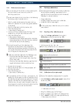
1.
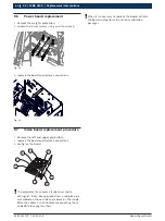
Remove the weights protection;
2.
Loosen the 5 rear screws using an allen wrench;
Fig. 22:
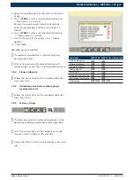
3.
replace the board and restore connections.
Fig. 23:
9.7
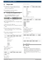
Video board replacement procedure
1.
Remove the left and upper protections;
2.
replace the board and restore connections;
3.
configure the board.
D
E
F
G
L
C
I
M
!
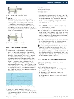
The piezo-electric sensors are identical and to
distinguish them, during production, a red pick-up is
assembled on the outside and a black on the inside.
Mark the cables F and G before reconnecting them
to be able to recognise them.
!
When it is necessary to replace the board, activate
the board and perform the various calibration
passages.


