Repair and Testing Instructions for T1 Page 32
Alternator 0120 689 552
Edition 001
All rights rest with Robert Bosch Corp, including patent rights. All rights of use of reproduction and publication rest with R. B. Corp.
UA/ASV
04.12.98
T1ALTFinal.DOC
10.5 Stator Assembly
1. Position the stator on the collector end shield. The side of the stator with the winding leads should be
closest to the collector end shield.
2. Line up the scribed mark of the stator with the scribed mark of the collector end shield. If either the stator or
collector end shield was replaced, a new mark should be scribe across the new part using the replaced
component as a reference.
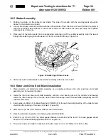
3. Place each of the stator leads into a corresponding soldering lug of the rectifier assembly. After the lead is
through the soldering lug, bend the lead so it forms a U around the lug. (Figure 35)
4. Solder each of the stator leads to the rectifier assembly with rosin core solder.
10.6 Rotor and Drive End Shield Installation
1. Place collector end shield and stator assembly on a suitable surface so the rotor and drive end shield
assembly can be lowered into place
2. Guide the rotor and drive end shield assembly until the inner bearing race of the collector end bearing
enters the roller bearing. Once the inner race enters the bearing, lower the assemblies completely into the
collector end shield.
3. Insert guide pin KDLJ 6014 (Bosch Number 0 986 618 128) through the sliding bushing of the collector end
shield and the bushing of the drive end shield. (Figure 36)
4. Start the four (4) drive end shield to collector end shield screws.
5. Place the alternator assembly into clamping fixture KDAW 9999.
6. Insert four (4) 0.3 mm (0.012 in) feeler gauges between the stator and the rotor. The feeler gauges should
be place in four diametrically opposed positions. (Figure 36)
7. Torque the drive end shield to collector end shield screws to 7.2 to 9.7 NM (21.2 to 28.3 in. lbs.).
Figure 35 Soldering of Stator Leads


