Repair and Testing Instructions for T1 Page 27
Alternator 0120 689 552
Edition 001
All rights rest with Robert Bosch Corp, including patent rights. All rights of use of reproduction and publication rest with R. B. Corp.
UA/ASV
04.12.98
T1ALTFinal.DOC
10 Alternator Assembly
10.1 Rotor Assembly
1. Position rotor in arbor press with the drive end pointing down.
2. Press the lead for the rotor winding into the slot of the rotor.
3. Slide the collector rings onto the rotor shaft as far as possible by hand. Make sure the lead for the rotor
windings does not become damaged while sliding the collector rings over the lead.
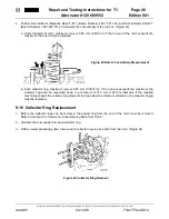
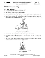
4. Lining up the slot in tool KDLJ 6012 (Bosch Number 0 986 618 126) with the rotor lead, press the collector
rings onto the rotor as far as possible. (Figure 25)
5. Solder each of the rotor winding leads to one of the collector rings with rosin core solder.
6. After soldering, touch up surface of collector ring to remove any excess solder from the brush contact
surface.
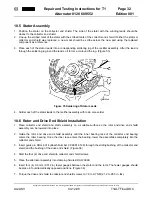
7. Press on collector end shield bearing spacer ring with tool KDLJ 6018 (Bosch Number 0 986 618 134) until
it contacts the stop on the rotor and no air gap is present. (Figure 26)
Figure 25 Pressing on Collector Rings
Figure 26 Spacer Ring
Installation


