Vertical Configurability
|
21
SM Series Heat Pump
6 720 220 406 (2015/02)
Revised 02-15
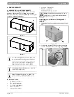
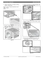
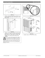
3. Locate the BACK left condensate drain and
remove and retain plastic plug covering the
cutout. (Figure#65)
Figure # 65
4. Reinstall the removed plastic plugs in the
original Condensate Drain Location.
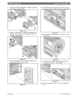
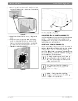
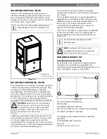
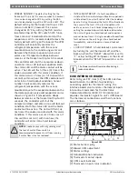
5. Route the flexible plastic tube from FRONT left
corner post to BACK left. (Figure#66)
Figure # 66
6. Measure and cut the condensate drain hose to
the appropriate length.
7. Insert spring onto condensate drain hose.
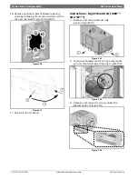
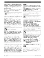
8. Reinstall condensate drain plastic fitting and
bushing in its new location.(Figure#67)
Figure # 67
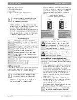
HRP Switch Relocation
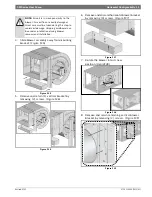
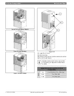
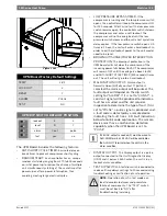
The HRP Pump Disconnect Switch is shipped loose
inside unit E-Box, to be connected to either FRONT
right corner post or BACK right corner
post.(Figure#68)
Figure # 68
1. From the inside of the unit remove (2) wires
connected to HRP Pump Disconnect Switch.
NOTE: Avoid kinking the hose and/or
creating a dip which could act as a second
internal p-trap. Double trapped drain lines
will not drain properly.

