SM Series Heat Pump
SM Series Heat Pump
6 720 220 406 (2015/02)
Subject to change without prior notice
24
|
Vertical Configurability
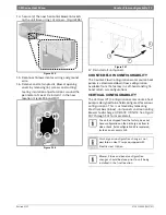
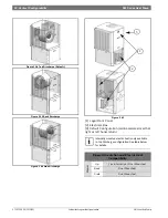
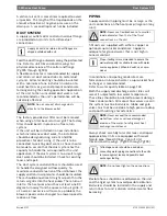
12. Reconnect high voltage wiring from Electric
Heat E-Box and Heating Element(s) matching
wire number to terminals as
shown.(Figure#80)
Figure # 80
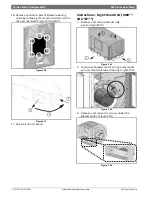
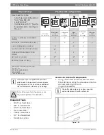
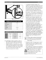
13. Re-install Electric Heat Elements Cover(s).
(Figure#81)
Figure # 81
Electrical Box re-configuration
E-box is designed to be removable to support field
configuration of unit: Left-Hand Return and Right-
Hand Return, and also to allow full access to
compressor during servicing.
The Electrical box (E-Box) has a set of plugs that
allows complete removal from the system while
keeping the majority of its internal connections.
(FIgure#123 & #124, Pg#72 and Pg#73)
1. Disconnect wiring harness by unplugging the
following plugs: P18, P19, P20 and P23 (P12 if
unit is equipped with Electric Heat).
(FIgure#123 & #124, Pg#72 and Pg#73)
2. Disconnect compressor plugs at compressor.
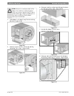
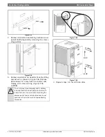
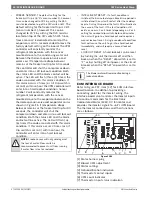
3. Remove and retain Electric Box by removing
(2) screws. (Figure #82)
Figure # 82
4. Reroute all of the disconnected wire bundles
to the opposite side of the heat pump.
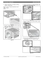
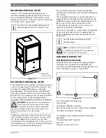
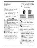
5. Install E-box in its new location by installing (2)
screws. (Figure #83)
Figure # 83
6. Reconnect all the wiring disconnected in Step
#1.
7. Identify and re-route LCD wiring harness to the
new location.
HT-4
HT-3
HT-2
HT-1
HLS-1
HLS-2
HLS-3
HLS-4
BLACK
RED
CAUTION: take great care to ensure all
wires are disconnected and none of the
wires are 'snagged' on any components
NOTE: Do not route wiring over potentially
hot surfaces or exposed sharp edges.
Damage to wiring could result.
NOTE: Ensure all connectors are properly
oriented and are fully engaged.
Panel containing LCD always mounts on the
same side as E-Box.

