


SM Series Heat Pump
SM Series Heat Pump
6 720 220 406 (2015/02)
Subject to change without prior notice
22
|
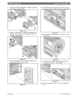
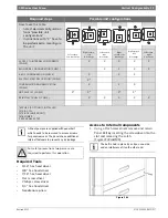
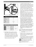
Vertical Configurability
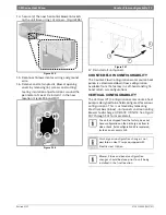
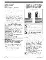
2. Identify a rectangular knockout and remove it.
Along with insulation.(Figure#69)
Figure # 69
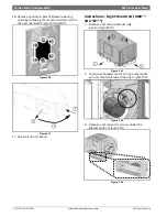
3. Route HRP Pump Disconnect switch wires to
the new switch location.
4. Install HRP Switch.
5. Reconnect the Switch wires.
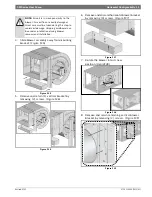
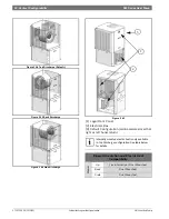
Electric Heat Relocation
When changing the unit from Left-Hand Return to
Right-Hand Return, it’s required to relocate
Electric Heat Components to the opposite side of
the blower in order to allow field servicing.
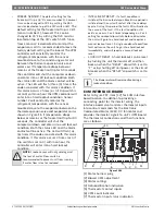
1. Identify Electric Heat components. (Figure#70)
Figure # 70
[1] Electric Heat Electrical Box
[2] Electric Heat Elements.
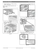
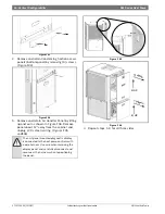
2. Remove and retain the Electric Heat Element
cover(s) by removing (4) screws in
each.(Figure#71)
Figure # 71
3. Disconnect high voltage wiring a the Electric
Heat Elements. (Figure#72)
Figure # 72
4. Remove and retain Electric Heat
Element(s).(Figure#73)
Figure # 73
NOTE: Do not route wiring over potentially
hot surfaces or exposed sharp edges.
Damage to wiring could result.
Electric Heat comes with (1) or (2) heating
element inserts, depending on capacity.
This instruction shows (1) heating element
insert. Perform the same steps for the
second insert, if present.
1
2