SM Series Heat Pump
SM Series Heat Pump
6 720 220 406 (2015/02)
Subject to change without prior notice
2
|
CONTENTS
Key to Symbols...................................................................3
Safety Warnings................................................................ 3
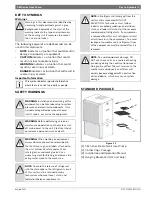
Standard package.............................................................. 3
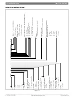
Model Nomenclature.......................................................... 3
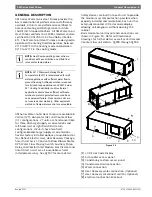
General Description........................................................... 5
Moving and Storage........................................................... 6
Initial Inspection ............................................................... 6
Location............................................................................ 6
Configurability .................................................................. 7
Horizontal Configurability.................................................. 7
Required Tools ............................................................ 7
Instructions - Left-Hand Unit (SM0**-1HZ-*L*-**) ............... 7
Instructions - Right-Hand Unit (SM0**-1HZ-*R*-**) ........... 10
Counter-Flow configurability............................................ 13
Vertical Configurability.................................................... 13
Required Tools .......................................................... 15
Access to Internal Components.................................... 15
Blower Re-Configuration............................................. 17
Condensate Drain Connection Re-configuration ............. 20
HRP Switch Relocation ............................................... 21
Electric Heat Relocation.............................................. 22
Electrical Box re-configuration ..................................... 24
Reinstall All Panels ..................................................... 25
Return and Discharge Duct Flanges .................................. 25
Pre Installation Unit Preparation ...................................... 26
Corner Cap Installation Instructions.............................. 26
Mounting Vertical Units ................................................... 27
Mounting horizontal Units ................................................ 27
Hanging Bracket kit..........................................................27
Condensate Drain............................................................ 28
Duct System.................................................................... 29
Piping ............................................................................. 29
Electrical ........................................................................ 30
Safety Devices and the UPM Controller ......................... 31
ECM INTERFACE BOARD ............................................ 35
Dehumidification Method Selector ............................... 36
Constant Torque Motors (ECM).................................... 36
Options........................................................................... 37
Hot Gas Reheat (HGRH).............................................. 37
Electric Heat ............................................................. 37
Heat Recovery Package (HRP) ..................................... 37
Constant Airflow Motor............................................... 38
DPS Water Flow Proving..............................................38
Pump Relay ...............................................................38
Comfort Alert Module .................................................38
Smart Start Assist.............................................................39
Mode of Operation Notes..............................................40
Heat Recovery Package....................................................41
Water Tank Preparation ..............................................41
HR Water Piping.........................................................41
Water Tank Refill ........................................................42
Initial Start-Up ...........................................................42
Sequence of Operation.....................................................43
Cooling Mode ............................................................43
Heating Mode ............................................................43
Application Considerations ..............................................45
Well Water Systems....................................................45
Cooling Tower/Boiler Systems .....................................45
Geothermal Systems ..................................................47
System Checkout.............................................................48
Unit Start-up....................................................................48
Maintenance ...................................................................49
Unit Check-Out Sheet.......................................................50
Customer Data...........................................................50
Unit Nameplate Data...................................................50
Operating Conditions..................................................50
Auxiliary Heat ............................................................50
Troubleshooting ..............................................................51
Electronic Thermostat Installation ....................................56
Operating Temperatures and Pressures ............................57
Airflow Tables..................................................................62
Water Side Pressure Drop Table........................................64
Wiring Diagrams ..............................................................65
WIRING HARNESS DRAWINGS ..........................................72
Constant Torque Motor (SM0**-***-***-T*)........................72
Constant Airflow Motor (SM0**-***-***-A*) .......................73
Spare Parts List ...............................................................74
Dimensional Drawings......................................................95
Horizontal - Straight Through .......................................96
Horizontal - Hanging bracket location ............................97
Counter Flow.............................................................98
CF Vertical ................................................................99


