RE 30011-B, Edition 10.2021, Bosch Rexroth AG
Alphabetical index |
Pressure and flow control system SYDFE1 series 2X, 3X
93/96
18 Alphabetical index
A
Abbreviations .................................... 8
Actual pressure value adjustment .... 68
Actual pressure value signal adjustment
Actual values ................................... 31
Actuating system supply .................. 17
Adjustment to the connected oil volume
Ambient conditions ......................... 27
Ambient temperature ...................... 27
at zero stroke pressure .................... 19
B
Basic operating modes .................... 19
Bleeding .......................................... 71
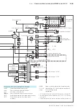
Block circuit diagram of control
electronics VT 5041-3X .................... 90
Brief regenerative operation ............ 24
C
Cabling ............................................ 52
Care ................................................ 73
Case drain piping ............................ 45
Check swivel angle “zero” ............... 70
Circulation operation ...................... 22
Cleaning .......................................... 73
Commissioning ................................ 59
initial ............................................ 60
Configuring switches and jumpers of
the VT 5041-3X ................................ 62
Connecting
electrically ................................... 52
hydraulically ................................. 48
Connecting the solenoid of the
proportional valve ........................... 58
Connecting the valve position
transducer ....................................... 55
Continuous regenerative operation .. 22
Control electronics VT 5041-3X
Block diagram .............................. 90
Functions ..................................... 30
Controller structure ........................ 19
Control mode
Message ....................................... 31
Conversion ...................................... 79
Coupling .......................................... 47
D
Damage to property
general notes ............................... 14
Data sheet ......................................... 6
Decommissioning ............................ 76
Demounting ..................................... 77
Demounting .................................. 77
Preparing ..................................... 77
Device description ........................... 16
Dimensions ..................................... 39
Connections ................................. 46
Direction of rotation ........................ 46
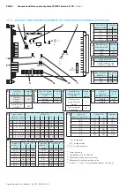
Display and setting elements of control
electronics VT 5041-3X .................... 92
Disposal .......................................... 78
Documentations ................................ 6
E
Enable ............................................. 30
Extension ........................................ 79
External pilot oil supply .................. 26
F
Fault message ................................. 31
Fault table ....................................... 85
Filling .............................................. 60
Filtration of the hydraulic fluid ........ 28
Flange pattern ................................. 50
Flushing .......................................... 61
Functional description .................... 16
Functional test ................................ 71
Function of pressure controller OFF or
master/slave .................................... 63
G
Gain of the actual pressure value .... 68
Gain of the pressure controller ....... 69
Generation of noise ......................... 28
H
Hydraulic fluid ................................. 60
Selection ...................................... 27
I
Identification of the product ........... 38
Inspection ....................................... 73
Inspection schedule ........................ 73
Installation
with coupling ............................... 47
Installation conditions ..................... 42
Installation drawing ........................... 6
Installation position ........................ 43
Intended use ..................................... 9
Internal pilot oil supply ................... 25
K
Keyed shaft ..................................... 29
L
Leakage compensation .............. 32
,
Lifting tool ...................................... 39

