RE 30011-B, Edition 10.2021, Bosch Rexroth AG
Commissioning |
Pressure and flow control system SYDFE1 series 2X, 3X
61/96
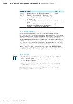
The SYDFE1 control system should be filled using a filling and filtration unit
(10 µm filtration rating). The control system must not be powered when being
filled.
1.
Fill and air-bleed the SYDFE1 control system via the appropriate ports, see
chapter 7.3 “Installation positions and piping of SYDFE1 systems” on page
43. The hydraulic lines of the system must also be filled.
2.
Test the direction of rotation of the drive motor. To do this, rotate the motor
briefly at the lowest rotational speed (inching). Make sure that the direction
of rotation of the SYDFE1 control system corresponds to the indication on the
nameplate, see also chapter 5.13 “Product identification”, Fig. 15 “Nameplate“
on page 38.
3.
Operate the SYDFE1 control system at low speed (jog mode) until the pump
system is completely filled and bled. For checking purposes, drain the hydraulic
fluid at the case drain port and wait until fluid flows out without any bubbles.
4.
Make certain that all ports are either connected to pipes or plugged according
to the general circuit diagram.
8.1.2 Testing the hydraulic fluid supply
The SYDFE 1 control system must always be supplied with sufficient hydraulic
fluid. For this reason, the supply of hydraulic fluid must be ensured at the start of
the commissioning process.
When you test the hydraulic fluid supply, constantly monitor the noise generation
and check the hydraulic fluid level in the tank. If the SYDFE1 control system
becomes louder (cavitation) or the case drain fluid flows out with bubbles, this
is an indication that the SYDFE1 control system is not sufficiently supplied with
hydraulic fluid.
Notes on troubleshooting can be found in chapter 15, “Troubleshooting“ on page
80.
To test the hydraulic fluid supply:
1.
Allow the drive motor to run at lowest speed. The SYDFE1 control system must
be operated under no-load conditions. Pay attention to leakage and noise.
2.
Check the SYDFE1 control system’s case drain line while testing. The case
drain fluid should not contain any bubbles.
3.
Check the suction pressure at port “
S
” of the SYDFE1 control system pump.
For the permissible value, please refer to data sheet RE 92050.
4.
Check the case drain pressure at connected port “
K
1
“ or “
K
2
“. For the
permissible value, refer to data sheets RE 30030 and RE 30630, respectively.
8.1.3 Performing a flushing cycle
To remove foreign particles from the system, perform a flushing run for the entire
system.
Flushing is to be carried out with a separate flushing unit. Observe the
instructions of the flushing unit manufacturer for the detailed procedure for
carrying out flushing.


