1
0
9
8
7
6
5
4
3
2
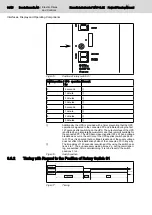
Fig.6-15:
Position of rotary switch S1
Switch position UPS operation
for
Remark
0
5 seconds
①
1
1 minute
①
2
2 minutes
①
3
3 minutes
①
4
5 seconds
②
5
1 minute
②
6
2 minutes
②
7
3 minutes
②
①
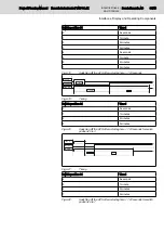
Additionally, the UPS is provided with a timer preventing that the UPS
operation is signaled to the connected PC and initiated during the first
120 seconds after switching on the UPS. The output voltage of the UPS
is buffered by an integrated accumulator and thus remains available for
the connected PC. The UPS becomes active after 120 s. When a voltage
breakdown occurrs, the set time of the UPS applies (switch position 0
to 3). Thus, it is ensured that a voltage breakdown of the supply voltage
does not effect the initialization phase of the connected PC in any way.
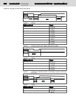
②
The time delay of 120 seconds is switched off by using the switch posi‐
tions 4 to 7. Thus, unnecessary waiting times, e.g. during commission‐
ing, are avoided. After commissioning, it is to be reset to the switch
positions 0 to 3.
Fig.6-16:
Switch position
6.6.2
Timing with Regard to the Position of Rotary Switch S1
+24 V In
24 V Out
> 120 sec.
5 sec.
t
UPS operation
Fig.6-17:
Timing
30/45
Bosch Rexroth AG | Electric Drives
and Controls
Rexroth IndraControl VAU 01.1Z | Project Planning Manual
Interfaces, Display and Operating Components

