
30
en | Installation wiring
PRAESENSA
2021.12.21 | V0.15b | F.01U.402.882
Underwriters Laboratories Listing Document (ULLD)
Bosch Security Systems B.V.
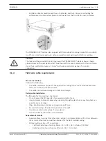
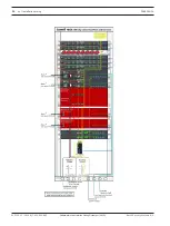
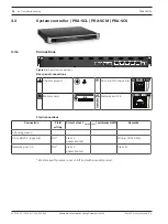
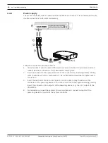
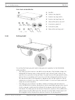
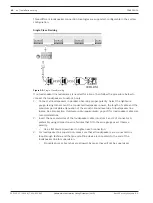
3.3.4
Power supply
The system controller must be powered from the MPSx 24 V output. It is recommended to use
double connections for fail-safe redundancy.
+
+
B
A
C
D
(MPSx)
C
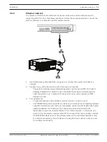
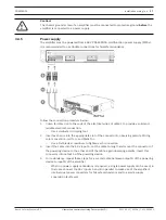
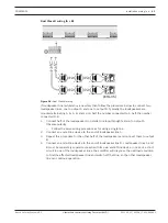
Follow the connection procedure below:
1.
Crimp ferrules D onto the ends of the electrical wires of cable C to provide a solid and
reliable electrical connection. Use a dedicated crimping tool.
2.
Insert each wire into the appropriate slot of the connector B, observing polarity. Wiring
color convention: red for + and black for -. Use a flat blade screwdriver to tighten each
connection.
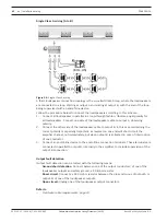
3.
Insert the cable into the 24 to 48 V input A, cut the cable to length and mount the
connector of the powering device to the other end of the cable, again observing polarity.
Insert this connector into output A of the powering device (e.g. the 24 V output of the
PRA-MPS3).
4.
For redundancy, repeat these steps for a second cable to connect output B of the
powering device to input B of the system controller.


