74
Presented by Bob Pattengale
BOSCH MTS 5200 LAB SCOPE
1-800-71-TRAIN (1-800-718-7246) OR www.auto-video.com
LIVE VEHICLE TESTING (TPS - GMM)
For this portion of the presentation we are going to take a closer look at the throttle position
sensor (TPS). The TPS is a very common sensor and when it fails you will usually have a
hesitation or problems that are very similar to hesitations.
The first thing we need to cover is the issues surrounding connecting to the sensor. There is no
one database or manual out there that has every sensor with the connections mapped out for us.
This is not as big of a problem as you might think.
If we know how a sensor works, it makes it much easier to diagnose what the problem might be.
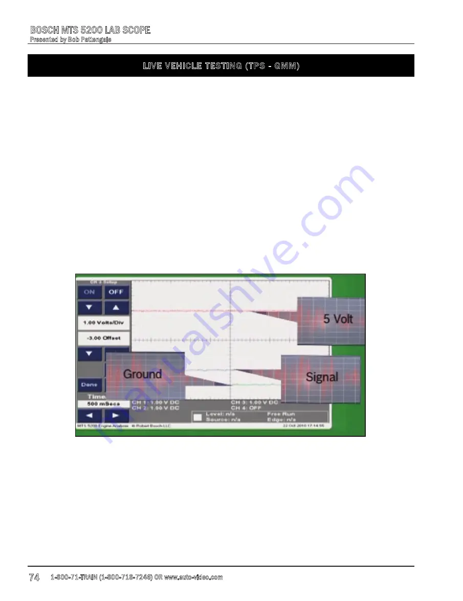
Most TPS are 3 wires. They have a 5 volt reference wire, a ground wire that would show 0.0 volts
and a 0.5 volt signal wire. The point we are trying to make here is this, by the time you look up
the wiring diagram for the vehicle you are working on, you could have already tested the sensor
with the lab scope and determined if the sensor was faulty or not. The fact remains that you still
would have needed to test the wires anyway.
If you understand the sensor and the circuit, all you need to do is probe the wire with the lab
scope and analyze the signal.
Pictured above is a screen capture of all three channels of the lab scope after we have back
probed the TPS harness connector. You can see that the top trace (red) is our 5 volt reference,
the middle trace (blue) is our signal and the bottom trace (green) is our ground.


