background image

12 


Use SDI video output 

Starting the Camera 

After you have mounted the camera properly, connect the camera to power. 
Each time the camera is powered on, it will perform a self-test to check the Pan/Tilt/Zoom (PTZ function). After self-test, 
you can operate the camera. 


NOTE!


The  self-test process starts after  the camera  is powered up.  Please 

wait patiently.


When the operating temperature is lower than zero degrees Celsius, the camera will be automatically pre-heat (the 
pre-heat process takes 30 minutes at most). The self-test starts only after the temperature rises above zero degrees 
Celsius.


Connect Camera to Monitor/SDI Device 


To view your camera, you need to use the coaxial cable to connect your camera to monitor or SDI device. 
* The monitor/device must support the signal of HD-SDI or 3G-SDI. 

Connect Camera with Controller 


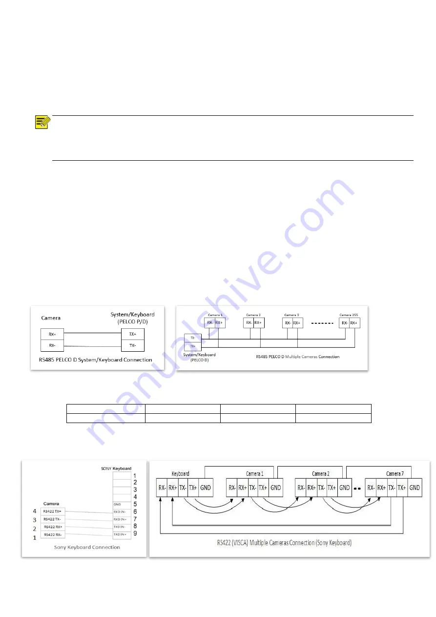
To control and configure your camera, you need to connect with control system (or control keyboard) by RS-485. 

1. Connection 

To control and configure your camera, you need to connect with control system (or control keyboard) for communication 
by RS-485/RS422. Set up the protocol of communication by control keyboard, the camera can auto detect VISCA and 
PELCO-D. 


1. Connection 

1.1 RS485 (PELCO D) control connection diagram 

Connect the Camera’s RS485+ and RS485 to RS485/TX+ and RS485/TX- on the control system/keyboard. The identity of 
the control system or equipment may be different; the corresponding relationship is as follows:  


RS-485 A 

RX+ 

RS-485 D+ 

RS-485 + 

RS-485 B 

RX- 

RS-485 D- 

RS-485 - 


1.2 RS422 (VISCA) control connection diagram 


SONY Keyboard RS422 Connection 


Summary of Contents for EX1000 Series

Page 1: ...1 EX1000 SDI IP SERIES IR LASER PTZ CAMERA USER MANUAL Part One Camera User Manual VERSION EXSN B M 10162017 2017 Bolin Technology ...

Page 2: ... THE CAMERA 10 LASER ILLUMINATOR 11 USE SDI VIDEO OUTPUT 12 STARTING THE CAMERA 12 CONTROLLING THE CAMERA 14 ADJUSTING AND SETTING WITH MENUS 14 THE ON SCREEN MENU CONFIGURATION 15 VIDEO FORMAT 19 USE IP VIDEO OUTPUT 23 SETTING CAMERA OVER THE LAN 23 ACCESSING YOUR CAMERA 23 INSTALLING THE ACTIVEX 24 DIMENSIONS 25 SPECIFICATIONS 26 ...

Page 3: ...he contents in this document but no statement information or recommendation in this manual shall constitute formal guarantee of any kind expressed or implied We shall not be held responsible for any technical or typographical errors in this manual The product appearance shown in this manual is for reference only and may be different from the actual appearance of your device This manual is a guide ...

Page 4: ...rface remove the dust gently using an oil free brush or a rubber dust blowing ball If there is grease or a dust stain on the front glass surface clean the glass surface gently from the center outward using anti static gloves or an oil free cloth If the grease or the stain still cannot be removed use anti static gloves or an oil free cloth dipped with detergent and clean the glass surface gently un...

Page 5: ...264 MJPEG RS485 RS422 Communication Auto compatible with PELCO D and VISCA Protocol Store image parameter iris white balance exposure picture setting to a specified preset 3D Positioning 120dB true WDR Video Output SDI IP True Dual Output SDI IP Simultaneously Adaptive IR laser illumination distance up to 500 Meters Outdoor Environmental Rating IP67 Corrosion Resistant Treatment Nitrogen Filled Ho...

Page 6: ...6 WHAT S IN THE BOX Accessories Optional ...

Page 7: ...7 Camera Diagrams Camera Tail Cable All cables are tagged to indicate their functions separately The cables available may vary with the product model ...

Page 8: ...vice model number and included contents against the packing list to ensure components are complete Camera Structure 1 Tail Cable 2 Camera Body Important Verify the bearing capacity of the mounted position Verify that the mounted position meets the bearing requirements Otherwise you are advised to reinforce the mounted position for the device weight For more information see the product datasheet Ve...

Page 9: ...he cable or to apply various kinds of stress to the cable so that the signal can be transmitted along the cable smoothly Different cable types have different physical characteristics and the transmission length of the digital signal is not the same Recommended cable Transmission signal Transmission distance Belden 7731A 3G SDI 120 m 128 above the double shield 75 5 HD SDI 70 m Power Input Bolin PT...

Page 10: ... PoE power up to the PTZ camera Connect this PoE injector to a network switch and then run Ethernet cable for data transmission and power up the PoE PTZ camera Specific model EX1000 SD500 Series for distance up to 100 meters NOTE Disconnect the power from the camera beforemounting Accessories such as the wall mount bracket and the pendant mount bracket may be necessary during mounting For their mo...

Page 11: ... illumination that provide the long distance visibility Precaution Specs 1 This product uses Class 3B laser light product 2 Supports Manual Auto IR laser control 3 Uses synchronous zoom with continuously adjustable illumination angle of 68 2 4 Supports intelligent light adjustment which automatically adjust the power of infrared laser light and avoids reflective object and close range image overex...

Page 12: ...nnect your camera to monitor or SDI device The monitor device must support the signal of HD SDI or 3G SDI Connect Camera with Controller To control and configure your camera you need to connect with control system or control keyboard by RS 485 1 Connection To control and configure your camera you need to connect with control system or control keyboard for communication by RS 485 RS422 Set up the p...

Page 13: ...ps 6 How to set up the address and baud rate of the camera for SDI please see the Page19 7 On the keyboard side for RS485 control go into the camera setting menu select the camera address ID you want to set up for set the baud rate to match the same as the one has been set on camera side select protocol Pelco D for RS485 control How to set up the menu of the keyboard please refer to the instructio...

Page 14: ...y vary according to the different product model numbers For a complete configurations menu see Menu Configuration NOTE You cannot perform pan tilt operations while the menu is displayed How to adjusting and setting by joystick of keyboard 1 Push the joystick of the keyboard to the up or down To select the menu that you want 2 Push the joystick of the keyboard to the right To enter the menu that yo...

Page 15: ...5 0 1 5 3 4 5 6 7 5 9 10 5 EXIT WHITE BALANCE AWB MODE AUTO INDOOR OUTDOOR OPW ATW USER R GAIN 0 255 B GAIN 0 255 EXIT PICTURE APERTURE 0 15 EFFECT OFF B W NEG EXIT LENS PARAMETERS DIGITAL ZOOM OFF ON JOYSTICK RECOVER NONE AF AI A I A F A F RECOVER 0 255 A I RECOVER 0 255 FOCUS NEAR LIMIT 1cm 10cm 20cm 30m DAY NITE MODE AUTO DAY NITE AUTO ICR THRESHOLD 0 28 GAMMA AUTO NORMAL 1 5 ZOOM SPEED 1 8 PRE...

Page 16: ...3 9 15 18 dB SPEED Select the electronic shutter speed from the following 1 1 1 2 1 3 1 6 1 12 1 25 1 50 1 75 1 100 1 120 1 150 1 215 1 300 1 425 1 600 1 1000 1 1250 1 1750 1 2500 1 3500 1 6000 1 10000 sec IRIS Select the iris the following CLOSE F14 F11 F9 6 F8 0 F6 8 F5 6 F4 8 F4 0 F3 4 F2 8 F2 4 F2 0 F1 6 LEVEL Select the brightness level from 0 to 23 BACKLIGHT MODE When the background of the s...

Page 17: ... white balance mode Select the white balance mode from the following AUTO IN DOOR OUT DOOR OPW One Push White Balance ATW Auto Tracing White Balance USER When you select USER R GAIN red gain and B GAIN blue gain appear You can select each item in the range from 0 to 255 EXIT Push the joystick to the right to exit this level menu PICTURE Menu The PICTURE menu is used to set the items related to the...

Page 18: ...be turned on at Night The image may be too dark to be seen in a low light condition When the camera is set to Night mode the camera will stay in Night mode Black White no matter how bright the lighting condition is the camera illuminator will be turned on all the time The image will be stay in Black White AUTO ICR THRESHOLD Set AUTO ICR THRESHOLD value to from 0 to 15 The sensitivity from low to h...

Page 19: ... 1080I 60 59 94 50 720P 60 50 30 25 S Class models 1080P 60 50 30 25 720P 60 50 30 25 IP output Select the IP video output format from the following 1080P 30 25 720P 30 25 Follow the steps to change the video format 1 Set SDI video resolution in SYSTEM SETUP 2 Select the SDI VIDEO format you want to have from 1080P 60 59 94 50 30 29 97 25 1080I 60 59 94 50 720P 60 50 30 25 3 Waiting for a while fo...

Page 20: ...NUMBER The current preset number that you are managing SET NEW PRESET To set up the preset of the above preset number 1 Push the joystick to the right to enter this setting menu you will see call preset 1 to end 2 Adjust the camera to the position that you want the camera to be and then call the preset 1 using the keyboard to save the position to be the current preset 3 Finished DELETE PRESET Dele...

Page 21: ... level menu PATTERN SETUP A pattern is a memorized repeating series of pan tilt zoom and preset functions that can be recalled with a command from a controller or automatically by a programmed function alarm park event or power up The menu is used to manage the patterns Total of 4 patterns can be managed PATTERN NUMBER The current pattern number that you are managing RECORD NEW PATTERN Set up the ...

Page 22: ...nt of IDLE Time the camera would take action automatically The menu is used to set the IDLE time and value can be selected from 0 to 255 sec IDLE ACTION After the IDLE time the camera starts the IDLE action automatically Even if the idle time s value is set to 0 or during the IDLE time manual operation will always have the priority to the response The menu is used to select the IDLE action The IDL...

Page 23: ...for your camera after you log in Accessing Your Camera For camera models with IP output you can manage and control through the web interface from a PC System Requirements for Your PC Item Requirements Operating System Microsoft Windows 8 Windows 7 Windows XP 32 bit or 64 bit Microsoft Windows 7 32 bit isrecommended CPU 2 0 GHz or higher dual core Intel i3 CPU or higher are recommended Memory At le...

Page 24: ...the ActiveX The following message will show in IE browser on first login Click Download to install Active X Click Run You may also click Save to download the file to your computer first Close the browser and follow the steps to complete the installation NOTE For your first login with Windows 7 if the system does not prompt you to install ActiveX follow these steps to turn off UAC Click the Start b...

Page 25: ...25 Dimensions Unit mm ...

Page 26: ...26 Specifications ...

Page 27: ...27 www bolintechnology com 2082 TECHNOLOGY LLC dba BOLIN TECHNOLOGY ...

Reviews: