
CS6140, CS6140B Series Turning machine
Instructions
15-2
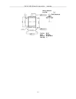
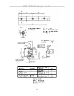
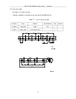
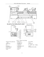
saddle (2) with 2-M6 screws and 2-10 taper pins. Bracket (9) is fastened to machine bed (10) with taper pins. When
operating, I-shaped sliding block (3) moves along plate (4) and sliding slot (5) moves along scale (6) that is
connected with graduation plate (7) with taper pins.
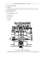
15.4 Setting up
Before using, the scale, which swings back and forth in the graduation plate around the shaft pin, must be
properly adjusted so that it points to correct graduation mark as required by the work piece to be turned. Rotate the
adjusting screw arbor till the scale is pointed in position, and fasten it to the graduation plate with two T-slot screws.
During operation the tool will move a taper path, thus a taper is turned. During taper turning some length of
cylindrical surface is always cut due to mechanical backlash. So it is necessary to take a test operation to find the
length (it varies with different taper work pieces). After setting up the tool, true turning cannot be taken unless the
said length is eliminated by moving the carriage a same distance to the right using the apron handwheel.
15.5 Caution
When the taper turning attachment is not to be used, bracket (8) must be removed. Some adjustment should
be made so that the scale is pointed to zero. Fasten T-slot screws (12) and lock I-shaped sliding block (3) using two
pointless set screws (13) to stop the drive screw from sliding back and forth.
When it is necessary to check the terminal block for trouble removing, take off the taper turning attachment
first.
Every running parts of the attachment should be lubricated with an oil gun every shift of work to reduce wear
and guarantee operation.
Summary of Contents for CS6140 Series
Page 16: ...CS6140 CS6140B Series Turning machine Instructions 4 3 Fig 4 2 Bearing location diagram ...
Page 31: ...CS6140 CS6140B Series Turning machine Instructions 6 2 Fig 6 1a Location of electrical parts ...
Page 33: ...CS6140 CS6140B Series Turning machine Instructions 6 4 Fig 6 2a Electric schematic diagram 1 ...
Page 34: ...CS6140 CS6140B Series Turning machine Instructions 6 5 Fig 6 2a Electric schematic diagram 2 ...
Page 48: ...CS6140 CS6140B Series Turning machine Instructions 10 2 ...


