CS6140, CS6140B Series Turning machine
Instructions
11-6
3
2
1
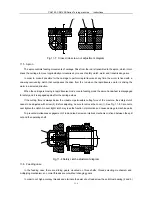
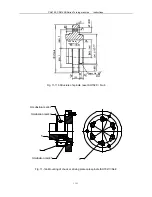
Fig.11-7 Cross slide screw nut adjustment diagram
11.5 Apron
The apron controls feeding movements of carriage. Drive from the rod is transmitted to the apron, which in turn
drives the carriage to move longitudinally or crosswise by means of safety clutch, worm and transmission gears.
In order to make it possible for the carriage to perform rapid traverse at any time the worm is fixed with a
one-way overrunning clutch that overpasses the drive from the rod when the rapid traverse motor is driving the
worm in a selected direction.
When the carriage is moving in rapid traverse mode or auto feeding mode the apron handwheel is disengaged
for safety and it is engaged again after the carriage stops.
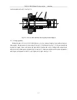
If the cutting force is always below the maximum permissible cutting force of the machine, the safety clutch
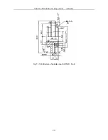
needs to be adjusted with screw (2). Before adjusting, be sure to remove the cover (1). See Fig. 11-8. Care not to
over tighten the clutch. An over tight clutch may lose the function of protection and cause damage to machine parts.
To prevent simultaneous engagement of rod and lead screw an interlock mechanism is fixed between the split
nut and the operating shaft.
1
1
2
Fig.11-8 Safety clutch adjustment diagram
11.6 Feeding case
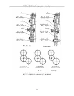
In the feeding case there are sliding gears mounted on three shafts, thread selecting mechanism and
multiplying mechanism, so normal threads are cut without changing gears.
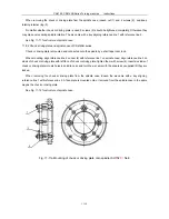
In order to cut high accuracy threads and eliminate the axial slip of lead screw the anti-thrust bearing (2 and 3)
Summary of Contents for CS6140 Series
Page 16: ...CS6140 CS6140B Series Turning machine Instructions 4 3 Fig 4 2 Bearing location diagram ...
Page 31: ...CS6140 CS6140B Series Turning machine Instructions 6 2 Fig 6 1a Location of electrical parts ...
Page 33: ...CS6140 CS6140B Series Turning machine Instructions 6 4 Fig 6 2a Electric schematic diagram 1 ...
Page 34: ...CS6140 CS6140B Series Turning machine Instructions 6 5 Fig 6 2a Electric schematic diagram 2 ...
Page 48: ...CS6140 CS6140B Series Turning machine Instructions 10 2 ...


