CS6140, CS6140B Series Turning machine Instructions
4-1
4 Machine drive system
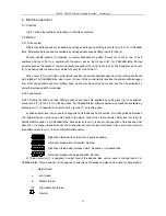
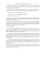
4.1 Tables and diagrams
Fig.4-1 shows the machine’
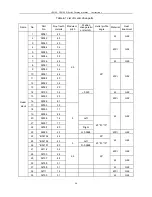
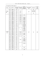
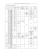
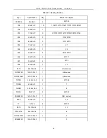
s drive system. Table 4-1 lists all the metric parts while Table 4-2 lists all the inch
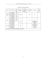
parts. Every bearing in drive system is listed in Table 4-3 and their positions are illustrated in Fig. 4-2.
Summary of Contents for CS6140 Series
Page 16: ...CS6140 CS6140B Series Turning machine Instructions 4 3 Fig 4 2 Bearing location diagram ...
Page 31: ...CS6140 CS6140B Series Turning machine Instructions 6 2 Fig 6 1a Location of electrical parts ...
Page 33: ...CS6140 CS6140B Series Turning machine Instructions 6 4 Fig 6 2a Electric schematic diagram 1 ...
Page 34: ...CS6140 CS6140B Series Turning machine Instructions 6 5 Fig 6 2a Electric schematic diagram 2 ...
Page 48: ...CS6140 CS6140B Series Turning machine Instructions 10 2 ...


