CS6140, CS6140B Series Turning machine Instructions
5-3
(1) Coolant supply ON/OFF button
(2) Emergency stop button
(3) Main motor start button
(4) Power switch
(5) End cover lever
(6) Feed selector lever
(7) Thread selector
(8) Spindle speed shifting lever
(9) Pitch and feed control knob
(10) Spindle speed shifting lever
(11) Pitch and feed knob
(12) Spindle control lever
(13) Apron handwheel
(14) Cross slide handle
(15) Tool post lever
(16) Work lamp switch
(17) Main motor control button
(18) Half nut lever
(19) Spindle control lever
(20) Compound rest handle
(21) Feed axis selector and rapid traverse button
(22) Coolant flow faucet
(23) Tailstock quill lock lever
(24) Tailstock clamping lever
(25) Tailstock handwheel
Fig. 5-1a Location and function of controls
Summary of Contents for CS6140 Series
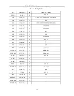
Page 16: ...CS6140 CS6140B Series Turning machine Instructions 4 3 Fig 4 2 Bearing location diagram ...
Page 31: ...CS6140 CS6140B Series Turning machine Instructions 6 2 Fig 6 1a Location of electrical parts ...
Page 33: ...CS6140 CS6140B Series Turning machine Instructions 6 4 Fig 6 2a Electric schematic diagram 1 ...
Page 34: ...CS6140 CS6140B Series Turning machine Instructions 6 5 Fig 6 2a Electric schematic diagram 2 ...
Page 48: ...CS6140 CS6140B Series Turning machine Instructions 10 2 ...


