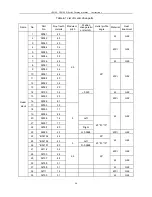
CS6140, CS6140B Series Turning machine Instructions
4-6
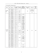
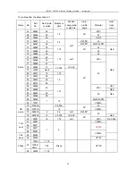
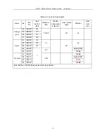
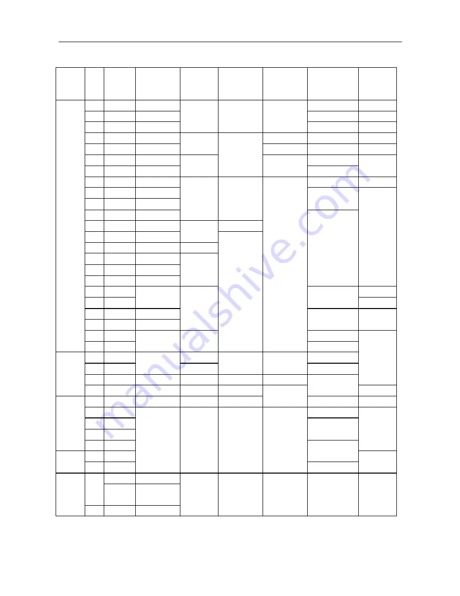
To continue from the above table 4-1
Name
No.
Part
No.
No.of teeth
or starts
Module or
pitch
Position
change ratio
or start dir.
Helix /
profile
angle
Material
Heat
treat-
ment
67
06061
36
40Cr
68
06062
32
45
69
06063
56
1.5
20°
GCr15
70
06057
2
6º20'25"
45
71
06021
26
2.5
6º20'25"
ZcuSn10Pb1
72
06064
32
45
73
06065
36
1.75
Left
20°
45
G48
74
06065
36
45
75
06066
45
76
06066
45
40Cr
77
06069
87
1.75
Left
78
06052
12
+0.249
79
01024
Rack
2.5036
80
06071
18
1.75
81
06072
28
82
06073
20
83
06074
89
1.5
45
G48
84
06066
G52
85
06066
45
40Cr
G48
86
06067
35
87
06068
58
1.75
45
G48
88
06022
ZcuSn10Pb1
Apron
89
01021
1
12
20°
Y40Mn
79
01024A
2.5036
45
89
01021A
12
20°
Y40Mn
70
06057A
2
2.5
Left
6º20'25"
RH
apron
78
06052A
12
2.5036
+0.049
45
G48
90
05031
18
1.75
Left
20°
40Cr
D0.3-550
91
05021
Y40Mn
92
05011
93
04011
HT200
Tool
post
94
04031
95
03022
Y40Mn
Tail-
stock
96
03005
1
5
HT150
15002
? 115
97
15002/
60Hz
? 93
Pulley
98
02003
? 175
B type
HT150
Summary of Contents for CS6140 Series
Page 16: ...CS6140 CS6140B Series Turning machine Instructions 4 3 Fig 4 2 Bearing location diagram ...
Page 31: ...CS6140 CS6140B Series Turning machine Instructions 6 2 Fig 6 1a Location of electrical parts ...
Page 33: ...CS6140 CS6140B Series Turning machine Instructions 6 4 Fig 6 2a Electric schematic diagram 1 ...
Page 34: ...CS6140 CS6140B Series Turning machine Instructions 6 5 Fig 6 2a Electric schematic diagram 2 ...
Page 48: ...CS6140 CS6140B Series Turning machine Instructions 10 2 ...


