CS6140, CS6140B Series Turning machine
Instructions
11-5
3
5
4
2
6
1
8
B
B
7
B-B
A
A
A-A
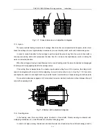
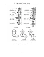
Fig. 11-6 Tailstock adjustment diagram
11.4 Carriage
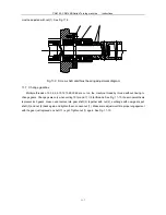
The cross slide is driven by the split nut which moves with rotation of lead screw and is used to eliminates
transmission clearance by adjusting the pith diameter fit. When adjusting loosen the stop screw
(2)
first and then
adjust screw
(1)
till the clearance is removed. After completion tighten screw
(2)
again and cover the dust lid (3).
See Fig.11-7.
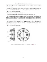
If the sliding ways of cross slide and compound rest have too large clearance or they are hard to move, adjust
the clearance with the adjusting screws at ends of the rack strip.
Summary of Contents for CS6140 Series
Page 16: ...CS6140 CS6140B Series Turning machine Instructions 4 3 Fig 4 2 Bearing location diagram ...
Page 31: ...CS6140 CS6140B Series Turning machine Instructions 6 2 Fig 6 1a Location of electrical parts ...
Page 33: ...CS6140 CS6140B Series Turning machine Instructions 6 4 Fig 6 2a Electric schematic diagram 1 ...
Page 34: ...CS6140 CS6140B Series Turning machine Instructions 6 5 Fig 6 2a Electric schematic diagram 2 ...
Page 48: ...CS6140 CS6140B Series Turning machine Instructions 10 2 ...


