background image

9


Troubleshooting 


9.5 

Blockage in the conveyor machine 


134 

6. 

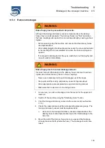
Check the delivery hose for other blockages (see Section 9.5.2). 

7. 

Make sure that there is no residual pressure in the delivery hose. 


A pressureless hose is soft and flexible. 


If there is residual pressure, the hose is firm. 

8. 

Loosen the couplings of the delivery hose in which the blockage was. 

9. 

Loosen the blockage by tapping, shaking and bending. 

10.  Shake the blockage out of the delivery hose. 

Several blockages 

Sometimes there are several blockages in the delivery hose.  

1. 

Deform the delivery hose to determine whether the delivery hose is 
depressurized. 

2. 

If there is a residual pressure, e.g. between two blockages in the 
delivery hose, move the delivery hose back and forth, tap the delivery 
hose and thereby help to reduce the residual pressure and thus to 
loosen the blockage. 

3. 

Make sure that the delivery hose can be deformed easily over its entire 
length. 

4. 

Loosen the couplings of the delivery hose in which the blockage was. 

5. 

Loosen the blockage by tapping, shaking and bending. 

6. 

Shake the blockage out of the delivery hose. 

7. 

If there is other blockage in the delivery hose, repeat this procedure. 


Summary of Contents for alpha CR

Page 1: ...er use 16 2 4 Obligations of the machine operator 17 2 5 Responsibility of personnel 18 2 6 Personal protective equipment 19 2 7 Residual hazards 20 2 7 1 Warning signs on the machine 20 2 8 Security risks 22 2 8 1 Risks from moving components 22 2 8 2 Risks from thermal hazards 22 2 8 3 Risks from noise 22 2 8 4 Risks from electrical current 23 2 8 5 Risks due to hazardous substances 23 2 8 6 Ris...

Page 2: ...ssis 36 4 4 Machine 44 4 4 1 Options 46 4 5 Functional sequence 47 4 6 Operating elements 48 4 6 1 Machine 48 4 6 2 Multifunction display 52 4 6 3 Scraper radio system 53 4 7 Menus 55 4 7 1 General display area 56 4 7 2 Main menu 57 4 7 3 Submenu 59 4 7 4 Diagnostic menu 60 4 7 5 Messages 62 5 Transport 63 5 1 Transport inspection 63 5 2 Transport restraints 63 6 Driving operation 64 6 1 Personnel...

Page 3: ... 109 7 7 6 Open the mixing and delivery vessel 111 7 8 Interrupting the delivery of mix 111 7 9 Stopping the working operation 112 7 10 Winter operation 116 8 Cleaning 117 8 1 Personnel 117 8 2 Personal protective equipment 117 8 3 Safety instructions for cleaning 117 8 4 Air extraction connection 118 8 4 1 Connection of an external device 119 8 5 Cleaning the machine 120 8 5 1 Cleaning the vessel...

Page 4: ... 5 4 Inspection every 1000 operating hours 152 10 5 5 Inspection every 1500 operating hours 155 10 6 Lubrication schedule 157 10 7 External inspections 159 10 8 Maintenance and repair work 160 10 8 1 Changing tyres 161 10 8 2 Checking the tyre pressure 162 10 8 3 Oil change compressor motor and hydraulic oil 163 10 8 4 Battery maintenance 164 11 Storage 165 11 1 Personnel 165 11 2 Personal protect...

Page 5: ...x 179 14 1 Declaration of conformity 180 14 2 Drawings 181 14 2 1 BMS alpha CR standard 181 14 2 2 BMS alpha CR B feeder 182 14 2 3 BMS alpha CR B S feeder scraper 183 14 3 Circuit diagrams 184 14 3 1 Circuit diagrams alpha E32 and alpha E63 184 ...

Page 6: ...Contents ...

Page 7: ...ce with all specified safety instructions and directives The operating instructions are the basis for all actions on the machine and the basis for all training courses that take place on the machine Personnel must therefore have read the operating instructions carefully before starting any work In addition the national accident prevention regulations applicable at the operating site of the machine...

Page 8: ...tructions the following clarifications on typographical conventions must be observed List First level bullet points Second level bullet points Instruction 1 Step 1 of the instruction 2 Step 2 of the instruction 3 Step 3 of the instruction The sequence of action steps must be adhered to Tips Tips for situations that allow you to work efficiently ...

Page 9: ... Explanatory symbols Indicates a hotline Indicates maintenance work Indicates an inspection e g before starting work as part of maintenance Indicates maintenance work that may be carried out only by service personnel see section 1 11 or by a specialist workshop authorized by BMS ...

Page 10: ... hazards and notes DANGER Designates a danger situation that results in severe physical injuries or death WARNING Designates a possible danger situation that can result in severe physical injuries or death CAUTION Designates a possible danger situation that can result in slight to moderate injuries NOTE Designates a situation that can result in material damage ...

Page 11: ...sportation storage assembly commissioning operation maintenance This applies in particular to the 1st inspection after 50 operating hours use of not approved incorrect spare parts that do not meet the manufacturers specifications 1 7 Copyright protection These operating instructions are protected by copyright for BMS Bau Maschinen Service AG The operating instructions include regulations and drawi...

Page 12: ...omer service Our customer service is available for technical information In addition our employees are always interested in new information and experiences that result from the application and which could be valuable for the improvement of our add on devices Tel 49 0 5242 9646 0 Fax 49 0 5242 9646 29 Email info bmsbaumaschinen de If questions arise in practice you can also contact BMS directly Ser...

Page 13: ...ed to as manufacturer Personnel Personnel are all persons who operate and work on the machine The different requirements for these persons are described in Section 1 11 System operator The operator is any natural or legal person who uses the machine or makes it available to third parties for use The operator is responsible for the safety of the operator or third parties during use ...

Page 14: ...pecialist personnel F Specialist personnel for electrical equipment E Service personnel S Chapters Safety and Technical data are an exception These chapters are relevant for all target groups Operating personnel Operating personnel are persons who were instructed thoroughly and verifiably by the operator in their assigned tasks and possible hazards Operating personnel are responsible for operating...

Page 15: ... regulations are capable of properly performing work on electrical systems detecting possible hazards independently and preventing personal and material damage from electrical voltage All works on the electrical equipment must principally only be carried out by a qualified electrician Service personnel Authorised service personnel of BMS Bau Maschinen Service AG are considered to be service person...

Page 16: ...ls Only the materials listed below may be mixed and transported with the machine Screed up to a grain diameter of 16 mm Other materials are permitted only in consultation with and with the written approval of the manufacturer The machine must not be operated in closed rooms due to the exhaust gases produced The compressed air connection may only be used to convey material to the machine Any other ...

Page 17: ...ith the current version of regulations adjust the operating instructions insofar as necessary to new regulations standards and operating conditions clearly regulate and define the responsibilities for installation operation maintenance and cleaning of the machine ensure that all employees working on the machine have read and understood the operating instructions In addition the operator must verif...

Page 18: ...chine have read and understood the operating instructions before starting to work for the first time use the stipulated protective equipment It must be checked regularly and replaced if damaged In particular hearing protection must be worn when operating the machine avoid abnormal postures when working Furthermore all employees working on the machine are within the scope of their tasks responsible...

Page 19: ...ruding parts predominantly as protection against getting caught by moving machine parts Do not wear rings necklaces or other jewellery Solid protective gloves To protect hands against rubbing abrasions scratches grazes cuts punctures or similar superficial skin injuries Safety footwear To protect feet against injuries from falling parts and against slipping and falling on slippery surfaces Ear pro...

Page 20: ...ones which cannot be avoided due to the construction of the machine are marked with warning signs 2 7 1 Warning signs on the machine CAUTION Risk of injury through illegible signs Labels and signs that have become blurred or illegible no longer sufficiently mark danger points and cannot indicate possible risks of injury Keep pictograms safety warning and operating instructions in perfectly legible...

Page 21: ...n explosion hazard At the cooling Warning of rotating components At battery and fuel tank Warning of flammable liquids On the exhaust machine Warning of harmful gases Protective conductor terminal Labelling connection point of the external protective conductor Next to the earthing screws Identifies the protective conductor connection ...

Page 22: ...ays wait until all components with a trailing movement have come to a standstill and residual energy is automatically dissipated 2 8 2 Risks from thermal hazards Components assemblies are integrated in the machine which become hot during operation There is a risk of burns when touching the hot surfaces Wear appropriate personal protective equipment when working on hot components e g motors Ensure ...

Page 23: ...orrect 2 8 5 Risks due to hazardous substances Health hazards can occur with incorrect handling of auxiliary and working materials oils greases etc Observe the operating material notes in the safety data sheets of the manufacturer Always wear the necessary personal protective equipment when handling auxiliary and operating materials When refilling use devices that prevent splashing and spilling Di...

Page 24: ...p button Figure 1 Position of the emergency stop button The emergency stop button 1 is a pushbutton which serves to switch off the machine in an emergency As soon as the emergency stop button is pressed the drive motor stops and the compressed air supply to hydraulics and compressor is closed We recommend closing the levers for the upper and lower air see Section 4 6 beforehand if possible After a...

Page 25: ... is equipped with a safety switch 1 This ensures that the machine can be operated only with the dome screen installed and closed The dome screen can be lifted out of the dome and swivelled to the side for work in the delivery vessel In this case the safety switch is open This status is displayed on the control panel ...

Page 26: ... towing vehicle via the breakaway cable 1 when the vehicle is in motion If the trailer is detached from the towing vehicle while driving the handbrake of the trailer is actuated via the breakaway cable 2 9 4 Hose To prevent the hoses of the risers from tearing off under their own weight they must be secured with the hose holders ...

Page 27: ...g against restarting described in the following Before starting work 1 Stop the machine 2 Disconnect the battery 3 Attach a warning to the control system and enter the name of the responsible person authorised to switch the machine back on in the label After completing the work 1 Reinstall all safety devices properly and check their function 2 Ensure that there are no persons at the danger points ...

Page 28: ...the written approval of the manufacturer Unauthorised modifications invalidate the declaration of conformity The warranty becomes void 2 13 Disposal Legal national and community regulations for environmental protection and disposal must be observed in the handling of the machine In company regulations must be compared with the appropriate manufacturer s information and adjusted if necessary Incorr...

Page 29: ...rmissible total weight 2 000 kg Support load 100 kg Max permissible support load 120 kg Axis ALKO B 2000 4 Axle load 2 000 kg Tyre pressure 4 bar Wheels 205 R14C Torque wheel bolt 150 Nm Chassis 2 5 t Weight actual 1 790 kg Permissible total weight 2 500 kg Support load 100 kg Max permissible support load 120 kg Axis ALKO B 2500 8 Axle load 2 500 kg Tyre pressure 4 5 bar Wheels 225 70R15C Torque w...

Page 30: ... weight 2 000 kg Support load 100 kg Max permissible support load 120 kg Axis ALKO B 2000 4 Axle load 2 000 kg Tyre pressure 4 bar Wheels 205 R14C Torque wheel bolt 150 Nm Chassis 2 5 t Weight actual 1 990 kg Permissible total weight 2 500 kg Support load 100 kg Max permissible support load 120 kg Axis ALKO B 2500 8 Axle load 2 500 kg Tyre pressure 4 5 bar Wheels 225 70R15C Torque wheel bolt 325 N...

Page 31: ...otal weight 2 000 kg Support load 100 kg Max permissible support load 120 kg Axis ALKO B 2000 4 Axle load 2 000 kg Tyre pressure 4 bar Wheels 205 R14C Torque wheel bolt 150 Nm Chassis 2 5 t Weight actual 2 000 kg Permissible total weight 2 500 kg Support load 100 kg Max permissible support load 120 kg Axis ALKO B 2500 8 Axle load 2 500 kg Tyre pressure 4 5 bar Wheels 225 70R15C Torque wheel bolt 3...

Page 32: ...ump Height volume 14 0 cm3 Max pressure 210 bar Tank capacity 20 l Hydraulic oil BMS Supercharger Air volume 6 m3 min Max pressure 9 bar Compressor oil BMS 46 max capacity 10 l Electrical system Voltage 12 V Battery 12 V 90 Ah Lighting voltage Depending on the version 12 V or 24 V Cooling Oil cooler 3 separate circuits for engine oil compressor oil and hydraulic oil System Open system Accessories ...

Page 33: ... data 3 Identification of the machine 3 3 33 3 3 Identification of the machine 3 3 1 Nameplate The nameplate serves to identify the machine and chassis It is located on the side of the machine Figure 4 Nameplate ...

Page 34: ...dard Feeder Feeder scraper Delivery scope Operating instructions Turned over Storage box Lubrication gun Equipment options GPS positioning machine Filter hood Air blast gun cleaning gun Silo construction and silo control Ball head coupling with lock In addition you will for all versions need a discharge stand hoses with couplings total length at choice The hoses must have a minimum diameter of 50 ...

Page 35: ...hly divided into two areas Chassis This includes the carriage shaft the chassis the mixing and delivery vessel and the feeder or feeder with scraper Machine This includes the structure with control panel as well as the drive cooler compressor unit hydraulic unit and battery Figure 5 Machine overview 1 Feeder scraper option 2 Mixing and delivery vessel 3 Axis 4 Carriage shaft 5 Setup ...

Page 36: ... Chassis Overview Figure 6 Chassis elements 1 Feeder option 2 Scraper option 3 Mixing and delivery vessel 4 Axle with wheels 5 Overrun device 6 Support wheel crank 7 Support wheel 8 Handbrake 9 Clutch with overrun brake 10 Plug 11 Brake shoe ...

Page 37: ...according to the StVO Certification For Germany the approval of the trailer with the assignment of its own registration number and the 2 year technical inspection by an approved testing centre is mandatory Outside Germany the respective registration guidelines of the country of registration must be observed Approval in other European countries is in accordance with the regulations applicable there...

Page 38: ...g vehicle s coupling device parallel to the ground Figure 7 Coupling device The chassis is optionally designed for transport with a ball coupling 1 usually for passenger cars or a DIN towing eye 2 usually for trucks or vans The integrated overrun brake brakes the trailer when the towing vehicle is braked and on steep downhill runs When braking the towing vehicle or driving downhill the draw bar of...

Page 39: ...oes Figure 9 Handbrake and brake shoes The handbrake 1 as well as the brake shoes 2 are used to safely stop the BMS alpha CR When parking the BMS alpha CR in connection with the towing vehicle the trailer must be secured with the handbrake If the parking area is not level or the trailer is standing without the towing vehicle it must be additionally secured with the brake shoes The trailer has 2 br...

Page 40: ...upport wheel crank 2 The support wheel must be turned out until the trailer is aligned horizontally Version II The support wheel 1 is used to park the trailer The support wheel is up when the trailer is in motion To park the trailer the support wheel is first turned down a little Pressing on the support wheel latch 3 folds it down until it engages in the lower position Turn the support wheel downw...

Page 41: ...rt I may be fitted When changing wheels the hub and wheel connection wheel type and wheel type must correspond exactly to the specifications in the vehicle registration document When using the BMS alpha CR in winter we recommend using M S tires or all season tires with the properties shown in the figure 3 Winter tyres are not mandatory status 10 2011 However in the event of an accident or getting ...

Page 42: ...nveyed mix The mixing shaft blades convey the mix into the delivery hose which is connected to the connection 3 after pressure has been applied in the vessel The delivery capacity can be further increased by means of the selectable power mode The mixing shaft is driven by the diesel motor via a pulley and gearbox The mixing time is set individually via the automatic mixing time control before star...

Page 43: ...g and delivery vessel The operating person can prepare the next mix during the delivery process thus enabling continuous operation The scraper 2 can only be mounted in combination with a feeder 1 The scraper considerably facilitates filling the feeder The scraper shovel is pulled through the sand pile by means of a steel cable and transports it into the lowered feeder Manual shovelling of sand or ...

Page 44: ...achine Overview Figure 14 Interior view of the structure 1 Separator 2 Screw compressor air filter 3 Hydraulics 4 Exhaust gas machine 5 Lubrication system 6 Filter cartridge 7 Compressor with controller 8 Cooling unit 9 Battery 10 Diesel motor ...

Page 45: ... at the set speed The screw compressor delivers the maximum air volume When the maximum set machine pressure approx 8 to 9 bar is reached the machine automatically shuts down and the screw compressor runs at idle At a lower pressure the screw compressor switches on again automatically If the pressure drops below 2 bar mixing vessel empty the screw compressor switches off in automatic mode In manua...

Page 46: ... is sufficient for approx 500 operating hours in standard operation 4 4 1 Options Filter hoods The filter hoods protect the cooling unit from rapid and excessive contamination by dust The filters also allow the cooling unit to be cleaned more quickly and easily Air blast gun cleaning gun The optional air blast gun cleaning gun can be used as a cleaning tool It is connected to the internal air extr...

Page 47: ...ery vessel and the delivery hose are pressurized with the compressed air generated by the compressor unit The upper air flows into the mixing and delivery vessel The lower air flows into the delivery hose The levers for the delivery rate of the upper and lower air are adjusted according to the delivery distance and delivery height The upper air in conjunction with the mixing blades forces the mix ...

Page 48: ...on 2 Start stop button motor 3 On Off button delivery 4 Pressure gauge compressor pressure 5 Pressure gauge vessel pressure 6 On Off switch mixer shaft 7 Multifunction display 8 On Off button power mode 9 Switch control on 10 Pull switch for work lamp 11 Lever raise lower feeder 12 Lever lower air flow rate 13 Lever upper air flow rate ...

Page 49: ...uge 4 This pressure display can be used to monitor the delivery process Possible blockages can be recognised when the compressor pressure drops Boiler pressure gauge 5 The pressure in the mixing and delivery vessel is displayed on the pressure gauge 5 The quantity of upper and lower air can be adjusted with the lever 10 and 11 only when the vessel pressure is sufficient When the lower air is open ...

Page 50: ...witch can be used to switch on the work lamp for the interior of the machine If you have switched on the work lamp it must be switched off at the end of work otherwise there is a risk of battery discharge Raising lowering the feeder lever 11 WARNING Risk of crushing in the swivel range of the feeder There is a risk of injury within the swivel range of the feeder when operating the lever for liftin...

Page 51: ...ssel Horizontal position The air supply of the lower air upper air is open Vertical position The air supply of the lower air upper air is closed The setting of the upper and lower air depends on several factors Delivery hose nominal diameter Type of hose coupling integrated inside or outside Delivery hose length Delivery head Composition of the mixture Type of delivery Consistency of the mix visco...

Page 52: ...n display 3 Machine wiring harness connection 4 Selector switch Deutz diagnostic interface 1 The Deutz readout device is connected to this diagnostic interface Selector switch The selector switch is used to navigate within and between the individual menus of the multifunction display By pressing the selector switch you can select buttons and acknowledge inputs ...

Page 53: ...transmitter 6 Thumb button LED display The LED display shows the different operating states of the radio system of the scraper Red LED If the red LED lights up an error has occurred or the address is changed Green LED If the green LED lights up the radio system is in operation It indicates the operating mode Yellow LED If the yellow LED lights up the battery is being charged ...

Page 54: ...tter via the thumb button until the red LED flashes 3 Press the button 3 again for 1 s The red LED goes out Resetting the address 1 Press the button 3 and keep it pressed for 3 seconds The address is reset Thumb button Via the thumb button the cable winch of the scraper is controlled As long as you keep the thumb button pressed the rope is rolled up by the winch If the thumb button is not actuated...

Page 55: ... done via the selector switch see Section 4 6 2 Selecting buttons 1 Highlight the button by turning the selector switch 2 Press the selector switch This turns functions on and off and calls up menus Enter the value 1 Highlight the button by turning the selector switch 2 Press the selector switch 3 Set the value by turning the selector switch 4 Press the selector switch to confirm the set value ...

Page 56: ...pressure display Shows the current motor oil pressure in bar 4 Mixture counter Shows the number of mixtures made The mixture counter is automatically reset when the machine is switched off 5 Diagnosis Shows the sum of the pending error codes 6 Key lock When the lock is closed the key lock is activated Deactivating the key lock 1 Press the selector switch 2 Press and hold the selector switch for 3 ...

Page 57: ...nt which does not lead to the motor being switched off Red An motor fault is present which prevents the motor from starting or causes the motor to be switched off 3 Compressor temperature check display Green The temperature of the compressor is within the permissible range Red The compressor is too hot over 120 C The machine switches off and starting is possible only after the fault has been recti...

Page 58: ... mixing time is running out Yellow When delivery is activated the control indicator lights up yellow until 2 bar minimum pressure is reached Green When delivery is activated the control indicator lights up green after the minimum pressure is reached 8 Power Mode Standard operation The OFF key is highlighted in grey Power mode The key ON is highlighted in blue The power mode is activated 9 Fuel gau...

Page 59: ... machine conveys permanently If the motor is running smoothly the button is displayed in green 3 Switch continuous lubrication on off 4 Call up the service area This area is accessible only to specialist personnel and is protected with a code The code entry menu opens after selection 5 Calling up the diagnostic menu The button displays the sum of the pending diagnostic codes 6 Switch the continuou...

Page 60: ...ates the subgroup of the SPN 3 OC OC means Occurrence Counter event counter This counter shows how often the SPN has occurred 4 BS BS means operating hours The operating hour during which the diagnostic code was reported is displayed 5 Calls up the Passive diagnostic codes menu The Passive diagnostic codes menu displays the diagnostic codes that are not currently pending 6 After selection the diag...

Page 61: ...ayed corresponds to the table columns in the Diagnostic menu see page 60 Figure 23 Diagnostic menu No Meaning 1 After selection the Passive diagnostic codes menu is closed and the submenu is displayed Machine internal diagnostic codes SPN FMI Meaning 0 100 Triggering of the compressor temperature switch 0 101 For 5 s no D signal with running motor 0 102 Emergency stop actuation for less than 1 s 0...

Page 62: ...ting the motor Remaining regeneration time The message appears during regeneration It indicates the remaining regeneration time xxxh Service This message is displayed shortly before the operating hours specified in the service interval are reached Pressing any key makes the service message disappear It is displayed again each time the machine is restarted Only after resetting the service confirmat...

Page 63: ...cept the machine or only under reserve Enter the extent of damage on the transport documents and note it on the delivery note of the transport company or in case of collection directly on the acceptance certificate Immediately enter a complaint for any defects upon receipt of the machine Claims based on transport damage can be asserted only within the valid complaint periods 5 2 Transport restrain...

Page 64: ...es to the chassis Modifications can lead to traffic accidents Make changes to the lighting tyres and rims only after ABE The machine may be moved only with the provided DIN towing eye or the ball head coupling The formation of white rust on the chassis does not cause any damage You can prevent the formation of white rust by ensuring sufficient ventilation or air circulation when parking the traile...

Page 65: ...e see Section 3 1 after 50 km of driving the tread depth of the tyres meets the requirements Tread depth according to regulation 1 6 mm BMS recommends a tread depth not less than 4 mm the rear light unit with number plate is mounted on the vessel and electrically connected the lighting machine is damaged or defective the on board voltage and lighting of the trailer and towing vehicle 12 V or 24 V ...

Page 66: ...d have sufficient braking power The towing vehicle must have the same on board voltage as the machine Coupling to a ball coupling is described in the following If a DIN towing eye is used coupling is carried out via the towing vehicle s coupling device Further information on coupling can therefore be found in the documentation of the coupling device 1 Secure the machine against rolling away with t...

Page 67: ...stance X is equal to the distance Y There are support wheel variants where you must first fold the support wheel downwards over the support wheel latch Figure 25 Aligning the carriage shaft 4 Pull out the spring cotter pins 5 by the locking levers 6 Figure 26 Adjustable overrun device 5 Release the locking levers 6 and turn them all the way up ...

Page 68: ... device Incorrect setting of the overrun device can interfere with the function of the brake system and thus lead to traffic accidents The overrun device must be parallel to the carriage shaft Check the safety of the carriage shaft clutch hand and overrun brake prior to each drive 7 Tighten the locking levers 6 and secure them with the spring pins 5 To ensure that the parking levers are firmly sea...

Page 69: ...nt otherwise the handbrake may be inadvertently applied when cornering 14 Check that the trailer is properly coupled Is the coupling engaged The marking must be in the green field If the marking in the red field is the trailer is not properly coupled If the marking in the red field is the coupling is defective In both cases where the marking is in the red field the trailer must not be used The cou...

Page 70: ...ore the stop until it engages Only then turn the support wheel upwards until it stops 16 Pull the locking device 1 backwards and fold the crank 2 upwards until it engages 17 Check whether the support wheel is dirty If necessary remove any adhering dirt 18 Mount the rear light unit with number plate by placing it on the bolts 8 on the mixing and delivery vessel and secure it with the locking spring...

Page 71: ...ower air Make sure that the plug is secured by the socket flap Figure 31 Electrical connection Pay attention to the lighting voltage 12 V 24 V 20 Connect the towing vehicle electrically to the trailer To do this insert the plug 11 from the trailer into the socket on the towing vehicle 21 Check the function of the lighting and brake system of the trailer ...

Page 72: ...tails Before each journey proceed as follows to prepare for driving 1 Remove the brake shoes and fix them in the brackets on both sides of the trailer 2 Close the hood of the machine and lock it with the clamping lever 1 Figure 32 Closing the hood 3 Check the closure of the canopy to ensure that no parts come loose while driving 4 Check that all spring cotter pins 2 are fitted to the scraper Figur...

Page 73: ...tion 6 2 7 Check the function of the lighting and brake system 8 Check tyre pressure and tyres 9 Check that the nameplate on the machine is clearly legible 10 Check whether the coupling device has the correct carriage shaft load and whether this corresponds to the towing vehicle 11 Make sure that the driver has the required driving licence class for the towing vehicle ...

Page 74: ... which the BMS alpha CR is used When driving the following points must be observed The trailer must not be tilted more than 25 in transverse direction danger of tipping over The trailer must not be tilted more than 20 from the horizontal in longitudinal direction driving direction The machine is designed so that the carriage shaft load reaches approx 50 of the permissible carriage shaft load The m...

Page 75: ...d Existence of sufficient free space for unhindered working e g correspondingly large distance to walls or other obstructions The necessary working space must be available for maintenance and service work There must be no explosive or other hazardous substances in the vicinity that can be sucked in Largely dust free environment There must be good ventilation so that no exhaust gases are sucked in ...

Page 76: ... using the handbrake make sure that it is always fully applied However the handbrake lever must not be in a vertical position A safe braking effect is guaranteed at a position of up to approx 70 for the applied brake As soon as the handbrake lever is in a position above 70 this means that the braking force has decreased In this case the brakes must be checked by BMS or a specialist workshop author...

Page 77: ... If necessary you can place a board underneath There are support wheel variants where you must first fold the support wheel downwards over the support wheel latch 6 Check whether the support wheel is dirty If necessary remove any adhering dirt 7 Remove the plug from the socket on the towing vehicle and connect it to the socket 6 on the carriage shaft Figure 36 Uncoupling the trailer 8 Detach the b...

Page 78: ...ure 37 Removing the rear light unit Parking in public places If you park the trailer with or without a towing vehicle in public places the rear light unit must be fitted correctly Figure 38 Parking in public places 1 Mount the rear light unit with number plate by placing it on the bolts 1 on the mixing and delivery vessel and secure it with the locking springs 2 2 Insert the plug of the rear light...

Page 79: ...e following points must be observed during longer periods of parking Cover the tyres when the machine is not in operation for a longer period of time Observe ventilation Clean the machine after it has been parked If necessary fit anti theft device If the trailer is parked in public places with or without a towing vehicle the rear light unit must be installed according to regulations ...

Page 80: ...trical components disconnect the voltage supply immediately and arrange for repairs Keep moisture away from live parts Work on electrical components must be carried out only by qualified electricians WARNING Risk of injury from inappropriate operation Inappropriate operation can lead to severe injuries The machine must be operated only by trained and operator authorized personnel Ensure that prote...

Page 81: ...rdous substances contain components that are hazardous to health and can lead to poisoning chemical burns or skin irritations Observe the manufacturer s safety data sheet Avoid spilling and fog formation Do not operate the machine in closed rooms WARNING Risk of injury from falling objects Objects can fall onto the operator from higher places Set up the machine at a sufficient distance Wear a prot...

Page 82: ...pprox 40 cm so that the hoses do not kink Install as few hose coupling points as possible Attach the risers very carefully with the hose holders provided so that the hoses do not break off under their own weight If in doubt secure all connected hose couplings against opening Check hoses and couplings regularly for wear For wear and ageing see maintenance list ...

Page 83: ... hoses Torn or broken or defective delivery hoses and couplings can cause personal injury and considerable material damage Only use delivery hoses with an operating pressure of at least 10 bar and a minimum diameter of 50 mm Do not use different minimum diameters This can lead to blockages The machine may be operated only with mounted discharge stand Use only approved and non defective delivery ho...

Page 84: ...tablishing hose connections For hose connections make sure that the rubber seals in the coupling sleeves are clean and present To make a hose connection open the two levers 3 folding out insert the plug 5 into the socket 4 and close the two levers 3 on the socket folding in The lock is secure When laying through rooms with passenger or building material traffic it is advisable to additionally secu...

Page 85: ...y the hose line shortly behind the machine using a secured support stand For longer level hose lines place a stand under the hose line approx every 20 metres Ensure that the support stand is securely connected to the ground so that it also serves to secure the hose line 5 Mount a discharge stand 6 at the end of the hose line 1 Figure 41 Mounting the discharge stand ...

Page 86: ... cloth Use a funnel when filling Only carry out work after the machine has cooled down sufficiently 2 Check the oil level on the diesel motor Proceed as follows Figure 42 Check oil level Pull out the oil dipstick 1 when the motor is warm and wipe it with a lint free cloth or absorbent paper Then insert the oil dipstick 1 and pull it out again after 10 s Carry out a visual inspection of the oil dip...

Page 87: ...ervoir 1 Figure 43 Checking the cooling water level If the level is below MIN an appropriate amount of water if necessary cooling machine protective agent must be topped up via the filler neck 2 Water quality and requirements for the cooling machine protective agent can be found in the manufacturer s manual for the diesel motor ...

Page 88: ...nd wipe it with a lint free cloth or absorbent paper Then insert the dipstick 3 and pull it out again Carry out a visual inspection of the dipstick 3 The hydraulic oil must be between the MIN and MAX marks If the level is close to MIN or below MIN a corresponding quantity of hydraulic oil must be topped up via the filler neck 4 The hydraulic oil must not exceed the MAX mark ...

Page 89: ...fuel tank if necessary Figure 45 Topping up fuel The fuel cap is secured with a cap The cap must be unlocked from the motor compartment NOTE The use of incorrect or impure fuel can lead to motor damage 6 Check the air filter 6 for dirt Replace the air filter and the safety cartridge if necessary Figure 46 Check the air filter ...

Page 90: ... be between the MIN and MAX marks If the level is near MIN or below MIN a corresponding quantity of compressor oil must be topped up The compressor oil must not exceed the MAX mark 8 Check the fill level in the supply tank of the central lubrication unit Top it up if necessary WARNING Risk of injury from moving components The fan blade continues to turn after the machine has been switched off and ...

Page 91: ...pulling it up Figure 48 Cooling unit The air filter consists of a metal stand which is attached to the base plate with magnets The filter cover should be cleaned regularly If you use the option filter hoods 10 the cooling unit 9 will not become so dirty An inspection is always necessary on a regular basis ...

Page 92: ...ke sure the rear light unit is dismantled Disassembly is described in Section 6 7 2 Loosen the safety catch on the feeder which is intended for transport To do this remove the lashing strap from feeder and mixing and delivery vessel Keep the lashing strap in a safe place Transporting the machine with the version feeder or feeder with scraper is not permitted without securing the lashing strap ...

Page 93: ...y Is the machine secured against rolling away Does the ground have sufficient bearing capacity Are all safety and protective devices fitted and functional Is the machine technically in order Are all cables and connections connected and secured Are all machine closures closed tank oil cooler battery filter etc Are all lubrication points greased sufficiently Is the central lubrication functioning pr...

Page 94: ... Start stop motor button on the control panel Press the button until the motor runs This can take a few seconds depending on the outdoor temperature If the motor switches off after the button is released repeat the starting procedure a few times Depending on the outside temperature minus temperatures max 5 times If the motor continues to stop after this check the fuel level compressor oil and moto...

Page 95: ...ger zones Never reach into running devices In particular never open the dome screen while the machine is running Never take the safety switch which protects against opening the dome sieve during operation out of operation Only carry out work when the dome screen is closed NOTE Never switch the machine off when it is full and leave it standing for a longer period of time Material may settle Therefo...

Page 96: ... directly standard via the feeder version with feeder or via the scraper version feeder with scraper Standard Figure 49 Filling the mixing and delivery vessel standard 1 Open the cover 3 of the filling dome 2 as far as it will go 2 Fold the hopper 4 onto the filling dome 2 of the mixing and delivery vessel 1 The toothing of the hopper 4 is used to easily tear open bagged material 3 Switch on the m...

Page 97: ...uring operation Do not stay within the swivel range of the feeder or its vicinity Do not decommission safety devices Wear the stipulated personal protective equipment WARNING Risk of crushing in the swivel range of the feeder There is a danger of crushing when the feeder is raised and lowered When working in the area of the feeder do not reach into or stay in the swivel range of the feeder Wear th...

Page 98: ... and swivel it downwards The feeder is lowered for filling 5 Fill the feeder with material sand gravel etc up to below the grid This corresponds approximately to one vessel filling NOTE The feeder is suitable only for filling with sand or gravel You must not add any binding agent or water to the feeder There is a risk of heavy soiling Cleaning is only possible with great effort A dirty feeder can ...

Page 99: ...quantity to the mixing and delivery vessel 1 10 Swivel the feeder upwards again via the Raise lower feeder lever 11 Fill the mixing and delivery vessel 1 with the remaining sand and gravel up to the lower edge of the filling dome 12 Swing the feeder down again using the Raise lower feeder lever The feeder can be refilled during the mixing and delivery time 13 Check the consistency and top up with ...

Page 100: ...es Wear the stipulated personal protective equipment WARNING Risk of crushing in the swivel range of the feeder There is a danger of crushing when the feeder is raised and lowered When working in the area of the feeder do not reach into or stay in the swivel range of the feeder Wear the stipulated personal protective equipment NOTE The dome cover of the mixing and delivery vessel must be open when...

Page 101: ...it will go 2 Fold the hopper 4 onto the filling dome 2 of the mixing and delivery vessel 1 The toothing of the hopper 4 is used to easily tear open bagged material 3 Switch on the mixing unit using the two position switch 4 Pull the Raise lower feeder lever horizontally out of its latch and swivel it downwards The feeder is lowered for filling ...

Page 102: ...the spring cotter pin in a safe place as transport is not permitted without securing 7 Take the scraper shovel out of the shovel holder and place the shovel in working position NOTE If the scraper is used to pull material that is outside the working area I in area II of the scraper there is increased rope wear The machine must be aligned with the sand or gravel pile Figure 53 Scraper working area ...

Page 103: ...l 7 you can influence the amount of sand to be transported 12 Pull the filled scraper shovel 7 over the ramp to the tipping point of the feeder 6 13 Switch off the winch by releasing the thumb button 8 14 Empty the scraper shovel 7 into the feeder 6 15 Repeat the process until the feeder 6 is filled NOTE The feeder is suitable only for filling with sand or gravel You must not add any binding agent...

Page 104: ...der upwards again via the Raise lower feeder lever 21 Fill the mixing and delivery vessel with the remaining sand and gravel up to the lower edge of the filling dome 22 Swing the feeder down again using the Raise lower feeder lever The feeder can be refilled during the mixing and delivery time 23 Check the consistency and top up with water if necessary 24 Fold the hopper back and clean the edge of...

Page 105: ...ones Replace a damaged rubber seal on the dome cover immediately 1 Make sure that the edge of the dome has been cleaned 2 Check the rubber seal on the dome cover for damage and replace it if necessary 3 Close the dome cover Figure 54 Dome cover closed 4 Fold the vessel vent 1 to the rear stop 5 Press the dome cover down on the handle 2 6 Press the toggle lock over the baffle 7 Push the lever 3 of ...

Page 106: ...justed while the machine is running Always set the mixing time before switching on the mixing unit Do not stay in or close to danger zones 2 Set the two position switch to the Mixing unit on position The necessary operating pressure builds up after the machine has been started The vessel pressure can be read off on the pressure gauges Likewise the belt tensioner which is pressurised tensions the d...

Page 107: ...is between 2 and 3 bar Delivery on level ground The optimum delivery pressure is between 3 and 4 bar In most cases a combination of different types of delivery is required In this case set the pressure range with the highest value 3 After the mixing time has elapsed follow up time according to the time setting if this option has been ordered delivery of the mix starts The motor runs at the set spe...

Page 108: ...chine switches off delivery and the compressed air The machine continues to run in the mixed operation function Delivery of the first mixture 1 Open the levers for upper and lower air completely 2 Switch on the automatic delivery machine via the Start Stop delivery button The machine builds up pressure and begins to convey slowly 3 Reduce the upper air and if necessary the lower air a little until...

Page 109: ...l pressure drops automatically After the vessel pressure falls below 2 bar fixed setting the compressor switches off No further air is delivered by the compressor The residual pressure of 2 bar remains in the mixing and delivery vessel Therefore before opening the dome cover it must be ensured that the mixing and delivery vessel is depressurized As the vessel ventilation 1 locks the toggle lock op...

Page 110: ... by the pressure drop The vessel pressure escapes via the venting system and is deflected to the ground through the venting hose 2 Venting during the delivery process The procedure for venting during the delivery process or in the event of a blockage is described in the following 1 Switch off the compressor with the Start stop delivery button 2 Slowly swivel the vessel vent 1 up see previous secti...

Page 111: ... cover using the handle 3 7 8 Interrupting the delivery of mix NOTE The mix may harden if work is interrupted for a longer period of time The time depends on the material properties Residues in the delivery hose and or in the mixing and delivery vessel can lead to blockages or block the mixing unit 1 Switch off delivery via the Start stop delivery button 2 Close the levers for upper and lower air ...

Page 112: ...xing and delivery vessel until empty Collect residual material and dispose of it in an environmentally friendly manner Follow the instructions for the material used 2 Wash the entire machine from the outside with water and a hand brush 3 Pump the mixing and delivery vessel empty at a low speed while adding clear water 4 Wash off any remaining material with a strong water jet 5 Switch off the motor...

Page 113: ... necessary 2 Preserve the feeder with a biodegradable BMS machine care product 3 Open the dome cover see Section 7 7 6 on this 4 Fold the hopper onto the filling dome of the mixing and delivery vessel See also Section 7 7 1 on this 5 Pull the Raise lower feeder lever horizontally out of its latch and swivel the feeder upwards until it is above the filling dome of the mixing and delivery vessel Fig...

Page 114: ... parts can cause severest injuries during operation Do not stay within the swivel range of the feeder or its vicinity Do not decommission safety devices Wear the stipulated personal protective equipment Figure 58 Installing the scraper 1 Release the pull rope 1 from the scraper shovel 2 Roll up the pull rope by pressing and holding down the thumb button 2 on the radio transmitter 3 Wash the outsid...

Page 115: ...is inserted into the charger at the end of work If the battery is defective send the device to BMS for repair 6 Open the dome cover see Section 7 7 6 on this 7 Fold the hopper onto the filling dome of the mixing and delivery vessel See also Section 7 7 1 on this 8 Pull the Raise lower feeder lever horizontally out of its latch and swivel the feeder upwards until it is above the filling dome of the...

Page 116: ...se winter diesel as fuel Due to special additives it is also flowable at low temperatures Summer diesel can gel in the lines and clog them Only use motor oil whose viscosity corresponds to the outside temperature If the temperature is extremely low remove the battery in the evening and store it in a warm room The battery may be reinstalled only shortly before starting the machine If the battery is...

Page 117: ... be life endangering With defective electrical components disconnect the voltage supply immediately and arrange for repairs Keep moisture away from live parts WARNING Risk of injury from unauthorized restarting Persons can be injured through an unexpected start up of the energy supply while working on individual components Before cleaning the machine it must be completely disconnected from the pow...

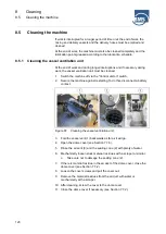
Page 118: ...governing environmental protections and disposal when handling cleaning agents and residual materials 8 4 Air extraction connection CAUTION Risk of injury from compressed air Compressed air can lead to injuries Never point compressed air at people Never use compressed air to clean clothing Do not use compressed air for breathing The machine is optionally equipped with an air blast gun cleaning gun...

Page 119: ...or could be damaged 1 Close the levers for the delivery rate of the upper and lower air 2 Switch off the mixer via the multifunction display Figure 60 Connect the cleaning device 3 Connect the cleaning gun cleaning device 1 to the quick coupling 2 of the air extraction connection 4 Switch on the voltage supply to the machine using the Control unit on switch 5 Set the machine to manual mode via the...

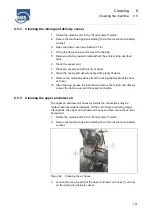
Page 120: ...it on switch 2 Secure the machine against restarting To do this disconnect a battery contact Figure 61 Cleaning the vessel ventilation unit 3 Fold the vessel vent 1 backwards as far as it will go 4 Open the dome cover see Section 7 7 6 5 Rinse the air vent 3 and the sealing cone 2 with plenty of water 6 Mechanically loosen stuck material residues with a scraper or similar Take care not to damage t...

Page 121: ...e material residues from the mixing shaft seals at the front and rear 10 After cleaning grease the lubrication points on the mixing and delivery vessel the dome cover and the vessel ventilation 8 5 3 Cleaning the upper and lower air The upper air and lower air hoses as well as the connections may be contaminated by material residues At the end of work and during longer interruptions the upper air ...

Page 122: ...es WARNING Risk of injury due to pressurized components The delivery hoses are under pressure and opening the hose couplings can cause severe injuries Before opening stop the machine and ensure that the delivery hoses are depressurized Wear safety goggles Residual pressures cause the conveyed material to be discharged at an accelerated rate when the hose couplings are opened If conveyed material g...

Page 123: ...the procedure if necessary 9 Switch the machine off via the Control unit on switch 10 Remove the material residues from the sponge rubber ball 11 Loosen the hose coupling at the vessel outlet and the hose couplings of the hose line 12 Clean the hose couplings with water and visually check them for damage 13 Clean the connection at the vessel outlet and visually check it for damage 14 Clean the out...

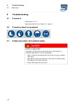
Page 124: ...tions for troubleshooting DANGER Electrical voltage hazard Touching live parts will lead to death Damage to the insulation or individual components can be life endangering Work on electrical components must be carried out only by qualified electricians With defective electrical components disconnect the voltage supply immediately and arrange for repairs Keep moisture away from live parts ...

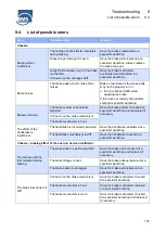
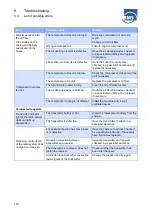
Page 125: ...at a specialist workshop and readjusted if necessary Corrosion on the brake mechanism The brake mechanism is bent The effect of the handbrake is insufficient The handbrake is incorrectly adjusted Have the handbrake readjusted at a specialist workshop The handbrake mechanism is stiff Have the handbrake checked at a specialist workshop Chassis braking effect of the overrun device insufficient The ca...

Page 126: ...ully retracted Gas dampers of the brake mechanism are defective Have the brake mechanism replaced in a specialist workshop Brake machine is set too tight Corrosion on the brake mechanism Have the brake mechanism checked at a specialist workshop The brake mechanism is bent Have the brake mechanism replaced in a specialist workshop Chassis ball coupling Ball coupling does not lock on the towing vehi...

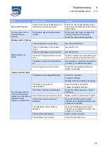
Page 127: ... switches electrical connections checked by a qualified electrician The mixing time is set incorrectly Check the mixing time setting and adjust if necessary Charge indicator light The charging indicator of the multifunctional display does not light up yellow when the machine is switched on The battery is discharged defective Check the acid level Charge the battery Replace defective battery if nece...

Page 128: ...alified electrician and replaced if necessary The starter motor is defective Check the starter motor and have it replaced if necessary There is too little fuel in the tank Check the fill level in the tank The fuel prefilter and or the fuel filter are dirty Check the fuel prefilter and or the fuel filter replace if necessary The dome screen indicator on the multifunctional display lights up red Che...

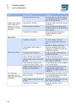
Page 129: ...rectly set Have the safety valve checked in a specialist workshop Air consumption exceeds the capacity of the compressor Air loss in the upper and lower air area Check air connections and air hoses The main air line is defective Have the main air line checked by a specialist workshop and repaired if necessary The vessel outlet is defective Check the vessel outlet and the air extraction connection ...

Page 130: ...ler The air deoiling device is blocked Have the air deoiling device checked in a specialist workshop and replaced if necessary The compressor cooling is insufficient Install the machine only in well ventilated areas Scraper radio system Transmitter indicator light of the radio system does not light up transmitter The transmitter battery is flat Insert the replacement battery from the charger The t...

Page 131: ...oided 9 5 1 Cause for blockage Blockages are caused mainly by Non pumpable material mixtures i e too lean or too thick Mixtures that have been standing for too long water and viscous material have settled Damaged or kinked delivery hoses Other possibilities for blockages are The nominal diameter of the delivery hoses does not meet the requirements The material and the nominal width of the delivery...

Page 132: ...s the mixing and delivery vessel is depressurized the delivery hose is also depressurized up to the first blockage in the hose line 1 Check starting from the outlet of the mixing and delivery vessel by carefully stepping on it and by pressing in the delivery hose where the blockage begins The hose is soft and easily deformed in the area where there is no blockage In the area where the blockage is ...

Page 133: ...f blockages in the delivery hoses can lead to serious injuries due to burst delivery hoses or hose couplings Never use compressed air to push blockages out of the hoses Stop work until the mixing and delivery vessel is depressurized Wear appropriate personal protective equipment during removal Make sure that no person is in the danger zone 1 As soon as you notice a blockage close the levers for th...

Page 134: ...s there are several blockages in the delivery hose 1 Deform the delivery hose to determine whether the delivery hose is depressurized 2 If there is a residual pressure e g between two blockages in the delivery hose move the delivery hose back and forth tap the delivery hose and thereby help to reduce the residual pressure and thus to loosen the blockage 3 Make sure that the delivery hose can be de...

Page 135: ...ry hose 2 Lay out the delivery hose at a slight slope so that any water that gets in can drain off 3 Push the water hose through the delivery hose against the escaping water The mix is dissolved by the water and runs out with the water 4 When no more material is rinsed out pull out the water hose 5 Check that all blockages have been removed If there are still blockages repeat the procedure until t...

Page 136: ...order to avoid blockages care must be taken when designing the delivery line and the composition of the mixture to ensure that use the delivery hoses tied up on the outside use delivery hoses with a larger nominal diameter produce mix with sufficient consistency As soon as you notice that the mix is conveyed only insufficiently or not at all you can add more water if the mix is too dry replace def...

Page 137: ... dispenser battery and machine battery is identical 12 V 2 Start the motor in the towing vehicle donor battery 3 Connect the positive terminal of the receiver battery to the positive terminal of the donor battery with a red booster cable 4 Connect the negative pole of the donor battery to earth bare metal part of the machine using the black booster cable 5 Start the motor of the machine see Sectio...

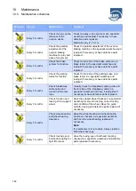
Page 138: ...t against restarting Keep moisture away from live parts Work on electrical components must be carried out only by qualified electricians WARNING Risk of injury from inappropriate maintenance Inappropriate maintenance can lead to severe injuries Observance of the maintenance intervals is decisive for the proper and durable functioning of the chassis and machine Maintenance work must be performed on...

Page 139: ...e hazardous to health and can lead to poisoning chemical burns or skin irritations Observe the manufacturer s safety data sheet Avoid spilling and fog formation Do not eat drink or smoke near the machine Avoid skin and eye contact WARNING Risk of injury from the high pressure system on the motor There is a risk of injury from improper disassembly or improper repair of the high pressure machine for...

Page 140: ...fications and welding work on pressure vessels are prohibited Incorrect or negligent disposal can cause considerable environmental pollution Have specialized companies dispose of electrical scrap electronics components lubricants operating supplies and other auxiliary materials Observe the handling and disposal regulations in the safety data sheets of hazardous substances Disposal must take place ...

Page 141: ...rried out by an authorised specialist company when the operating hours are reached Repairs may only be carried out by persons who are technically qualified and have the necessary qualification Maintenance repair work and inspections must be recorded in writing after they have been carried out The following must be specified work carried out parts used performing workshop status of the operating ho...

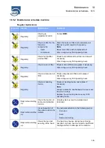
Page 142: ...age caused by construction site operation Before driving Perform a visual inspection of the rear light unit for the following items Illuminant undamaged Cables and plug connections Replace defective or damaged illuminants cables and plug connections Before driving If an optional feeder is used secure it against sagging with a lashing strap Observe road traffic regulations Before driving Secure the...

Page 143: ...t workshop Before driving weekly Check function and locking of the support wheel Check support wheel for damage Replace a damaged support wheel In case of malfunction contact a specialist workshop Before driving weekly Check function and tightness of the towing eye or ball coupling If the coupling or ball head of the towing vehicle is damaged contact a specialist workshop Every 1000 km or monthly ...

Page 144: ...ter in a specialist workshop and readjust if necessary or have defective parts replaced Every 3 months Check breakaway cable guide and function of the tear rope Visually check the breakaway cable guide and the function of the breakaway cable in a specialist workshop and have it readjusted if necessary or have defective parts replaced Every 3 months Check function and locking of the support wheel H...

Page 145: ...ilter change every 500 operating hours Regularly Check compressor oil filter Check compressor oil filter and replace if necessary Filter change every 500 operating hours Regularly Check air deoiling device Check air deoiling device and replace if necessary Note Always replace the seal between the cover and the tank housing Replace the air deoiling device every 1000 operating hours Daily before sta...

Page 146: ...ne protective agent according to the manufacturer s specifications Daily before starting up Check hydraulic oil level Check the hydraulic oil level with the oil dipstick in cold condition see Section 7 5 The hydraulic oil level must be between min and max If necessary top up hydraulic oil up to the max mark Daily before starting up Check compressor oil level Check the oil level with the oil dipsti...

Page 147: ...belt and power belts Tighten V belts if necessary Have damaged belts replaced in a specialist workshop Weekly Check the upper and lower air lines for dirt and clean them if necessary Air lines must be removed see Section 8 5 4 Weekly Check check valves for dirt The non return valves can be checked for soiling by looking into the connections with the top and bottom air hoses removed If they are dir...

Page 148: ...okes from the grease gun Weekly Grease lubrication points Grease must escape through the bearings after lubrication Otherwise a defective lubrication line may prevent the bearings from being greased Weekly Check the steel cable of the scraper shovel In case of damage including individual torn steel threads replace the steel cable 14tägig Check the grease nipples of the tensioning rocker in the mot...

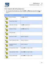
Page 149: ...l Maintenance Comment Engine oil change Use BMS motor oil Change motor oil filter Compressor oil change Use BMS compressor oil Hydraulic oil change Use BMS hydraulic oil Change fuel filter Check motor air filter Replace if necessary Check compressor air filter Replace if necessary Check gas distributor ventilation Clean if necessary Change separator oil filter Specify BMS no chassis number Change ...

Page 150: ...essary Check motor and compressor mountings Replace if necessary Check tyre pressure Tyre pressure see Section 3 1 Check overrun brake Check adjust if necessary Check contacts of lighting and illuminants Clean replace contacts if necessary Replace illuminant if necessary Grease lubrication points BMS lubrication points according to lubrication schedule Top up central lubrication BMS grease cartrid...

Page 151: ...er and lower air hoses BMS Check check valves for dirt BMS Check vessel vent Check 2 bar switch off BMS Check dome cover bearing Replace if necessary Check cover seal on dome cover BMS Check bearing of toggle lock Replace if necessary Check hopper bearing Replace if necessary Maintenance is part of the maintenance kit no W 500 BMS alpha CR ...

Page 152: ...intenance Comment Engine oil change Use BMS motor oil Change motor oil filter Change fuel filter Check motor air filter Replace if necessary Check compressor air filter Replace if necessary Change the air deoiling device Check gas distributor ventilation Clean if necessary Change hydraulic oil filter Hydraulic oil change Use BMS hydraulic oil Check V belt alternator Replace if necessary Specify BM...

Page 153: ...or replace if necessary Check motor and compressor mountings Replace if necessary Check power belt and belt relief BMS Check gearbox holder for deformation Adjust if necessary Check tyre pressure Tyre pressure see Section 3 1 Check overrun brake Check adjust if necessary Check contacts of lighting and illuminants Clean replace contacts if necessary Replace illuminant if necessary Grease lubricatio...

Page 154: ...k dome cover bearing Replace if necessary Check hopper bearing Replace if necessary Check bearing of toggle lock Replace if necessary Check hydraulics hoses valves motor pump Only for BMS alpha CR B and BMS alpha CR B S Seal or replace if necessary Check hydraulic return filter display Change filter and hydraulic oil if necessary Maintenance is part of the maintenance kit no W 1000 BMS alpha CR ...

Page 155: ... BMS motor oil Change motor oil filter Change fuel filter Check motor air filter Replace if necessary Check V belt alternator Replace if necessary Specify BMS no chassis number Check hose clamps on cooling machine and motor If leaking tighten and replace if necessary Check radiator for dirt Wash out if necessary Check battery acid level Top up the acid level if necessary Check electrical connectio...

Page 156: ...and illuminants Clean replace contacts if necessary Replace illuminant if necessary Grease lubrication points BMS lubrication points according to lubrication schedule Check hydraulics hoses valves motor pump Only for BMS alpha CR B and BMS alpha CR B S Seal or replace if necessary Change hydraulic oil filter Hydraulic oil change Use BMS hydraulic oil ...

Page 157: ... as some greases are not compatible with each other They gum up and the lubricating effect decreases drastically In addition follow the enclosed manufacturer s instructions for the motor axle and carriage shaft Position Lubrication point activity Figure Chassis Lubricate support wheel version I via grease nipple Quantity 1 pcs Lubricate support wheel version II via grease nipple Quantity 1 pcs Lub...

Page 158: ...ase nipple Quantity 1 pcs Machine Lubricate dome cover via grease nipple Quantity 2 pcs Lubricate clamping lever via grease nipple Quantity 2 pcs Lubricate funnel via grease nipple Quantity 1 pcs Feeder Lubricate lifting cylinder via grease nipple Quantity 2 pcs top and bottom Lubricate cardan shaft via grease nipple Quantity 4 pcs ...

Page 159: ...vessels Expert Has already been performed by BMS annually if required Expert inspection according to BGR 183 or BetrSichV of 27 09 2002 24 months Demonstration of the machine for examination of traffic safety Approved monitoring agency e g TÜV Dekra 24 months External inspection of the mixing and delivery vessel Expert Pressure Vessel Regulation Group IV 60 months Internal inspection of the mixing...

Page 160: ...ssel pressure at the pressure gauge see Section 7 7 5 3 Close the upper and lower air by means of the corresponding levers see Section 4 6 4 Check that the delivery hoses are depressurized 5 Switch the control unit off using the Control unit on button To prevent the machine from being switched on again unexpectedly and unintentionally secure the machine against being switched on again during maint...

Page 161: ...er we recommend having a spare wheel in the towing vehicle Figure 64 Changing tyres 1 Turn off the machine 2 Apply the parking brake and place the brake shoes under the stationary wheel 3 Slightly loosen the wheel nuts 1 of the wheel to be changed 4 Use a jack 2 to jack up the trailer on the corresponding side The contact points 3 for the jack 2 are located under the axle as close as possible to t...

Page 162: ...heel nuts after driving approx 50 km Use a torque spanner and observe the tightening torques for the wheel nuts 10 8 2 Checking the tyre pressure 3 Connect a compressed air supply to the valve of the tyre via a compressed air hose with pressure gauge 4 Read the pressure on the pressure gauge 5 If the pressure differs from the specified tyre pressure see Section 3 1 adjust the tyre pressure with th...

Page 163: ...ng the machine must be disposed of in a professional and environmentally friendly manner Disposal must take place in accordance with the applicable national rules and regulations In case of doubt consult the manufacturer or obtain information on the environmentally responsible disposal from the local authorities or disposal specialists We recommend having all oil changes carried out by BMS or a sp...

Page 164: ... safety data sheets of hazardous substances Disposal must take place in accordance with the applicable national rules and regulations In case of doubt consult the manufacturer or obtain information on the environmentally responsible disposal from the local authorities or disposal specialists 1 Check the liquid level of the battery The electrolyte level must reach the mark or the liquid must be 10 ...

Page 165: ...If the machine is stored it must be adequately protected against dust and dirt It must be stored in a frost free clean dry room The following must be observed here Clean the BMS alpha CR thoroughly Cover the tyres and check the tyre pressure at regular intervals Ensure sufficient ventilation at the storage location Store the machine in a dry and clean place Check the operating supplies levels Top ...

Page 166: ... cleaner and then preserve the machine Remove any additional heavy oil encrustations inside the machine with a cold or lime cleaner Maintain the motor as described in the enclosed manual of the manufacturer Jack up the machine during longer standstills to relieve the tyres and prevent deformation Grease all moving parts on the chassis and spray the machine with preservative ...

Page 167: ...he local authorities or disposal specialists 1 Store the machine in a dry well ventilated location 2 Let the motor warm up and then switch it off 3 Clean the oil exhaust filter if necessary 4 Fill up with anti corrosion oil instead of the normal motor oil 5 Drain the fuel from the tank 6 Fill the tank with a mixture of 90 diesel fuel possibly winter diesel and 10 anti corrosion oil 7 Let the motor...

Page 168: ...m in accordance with the regional or national regulations of the country of use Incorrect or negligent disposal can cause considerable environmental pollution Observe the information on disposal in Chapter 2 In case of doubt consult the manufacturer or obtain information on the environmentally responsible disposal from the local authorities or disposal specialists ...

Page 169: ...al versions 12 alpha E32 and alpha E63 12 1 169 12 Optional versions 12 1 alpha E32 and alpha E63 This section describes the special features of alpha E32 and alpha E63 Figure 65 View alpha E32 and alpha E63 ...

Page 170: ...nd alpha E63 170 12 1 1 Interior view Figure 66 Interior view alpha E32 and alpha E63 1 Electric motor 30 kW 2 Compressor 3 Oil filter 4 Cooler 5 Current connection 6 Central lubrication system 7 Oil container 8 Oil separator 9 Air Filter ...

Page 171: ...gnation Designation Component Allocation Q1 Main switch F1 Main fuse F2 Fuse Transformer F3 Fuse Transformer F4 Fuse Transformer 12 V DC F5 Fuse Start F6 Fuse Lubrication system F7 Fuse Headlights F8 Fuse Motor control F9 Fuse Machine control KM1 Main contactor K1 Relay Vessel safety switch K2 Relay Compressor motor start K3 Relay Safety chain K4 Relay Sponsorship K5 Relay Release radio etc ...

Page 172: ... pressure shutdown K3T Time relay Mixing time K4T Time relay Lubrication system 12 1 3 Operating elements Figure 68 Operating elements alpha E32 and alpha E63 1 Main switch 2 LED display 3 On Off switch mixing unit 4 Button Compressor on 5 Pressure gauge compressor pressure 6 Pressure gauge vessel pressure 7 Button Compressor off 8 Emergency stop button ...

Page 173: ... closed On Off switch mixing unit 3 This is a two position switch It switches the mixing unit in the mixing and delivery vessel on off Button Compressor on 4 The delivery of the compressor is switched on via the button 4 Pressure gauge compressor pressure 5 The compressor pressure is displayed on the pressure gauge 4 This pressure display can be used to monitor the delivery process Possible blocka...

Page 174: ...ery or in the event of a blockage Emergency stop button 8 The emergency stop button is a rotary switch for switching off the machine in an emergency If the emergency stop button is actuated the machine switches off immediately The drive motor stops and the hydraulics and compressor do not build up pressure Before restarting the machine the cause that led to the emergency stop must first be elimina...

Page 175: ...an cause tripping hazards Cover the cables with plastic cable bridges or feed cables from above If possible lay energy supply lines so that they do not pose a hazard for transportation and passenger traffic Observe the regulations of the trade associations especially the accident prevention regulations Observe the following points when connecting the power The power connection may only be made wit...

Page 176: ... following points for the delivery hoses and their routing Only use approved delivery hoses and hose couplings with a minimum diameter of 50 mm an operating pressure of 10 bar and a burst pressure of 40 bar To prevent blockages do not use delivery hoses with different nominal diameters When setting up the machine and when laying the cables make sure that no employees or persons outside the company...

Page 177: ...sor unit 45 Figure 16 Operating elements 48 Figure 17 Rear side multifunction display 52 Figure 18 Scraper radio system 53 Figure 19 General display area 56 Figure 20 Main menu 57 Figure 21 Submenu 59 Figure 22 Diagnostic menu 60 Figure 23 Diagnostic menu 61 Figure 24 Turn the support wheel downwards 66 Figure 25 Aligning the carriage shaft 67 Figure 26 Adjustable overrun device 67 Figure 27 Align...

Page 178: ...elivery vessel feeder 98 Figure 51 Open the mixing and delivery vessel 101 Figure 52 Removing the scraper shovel 102 Figure 53 Scraper working area 102 Figure 54 Dome cover closed 105 Figure 55 Venting the mixing and delivery vessel 110 Figure 56 Open the dome cover 111 Figure 57 Feeder transport restraint 113 Figure 58 Installing the scraper 114 Figure 59 Transport restraint feeder scraper 115 Fi...

Page 179: ...Appendix 14 List of figures 13 1 179 14 Appendix Declaration of conformity Drawings Circuit diagrams ...

Page 180: ...14 Appendix 14 1 Declaration of conformity 180 14 1 Declaration of conformity ...

Page 181: ...Appendix 14 Drawings 14 2 181 14 2 Drawings 14 2 1 BMS alpha CR standard ...

Page 182: ...14 Appendix 14 2 Drawings 182 14 2 2 BMS alpha CR B feeder ...

Page 183: ...Appendix 14 Drawings 14 2 183 14 2 3 BMS alpha CR B S feeder scraper ...

Page 184: ...14 Appendix 14 3 Circuit diagrams 184 14 3 Circuit diagrams 14 3 1 Circuit diagrams alpha E32 and alpha E63 ...

Page 185: ...Appendix 14 Circuit diagrams 14 3 185 ...

Page 186: ...14 Appendix 14 3 Circuit diagrams 186 ...

Page 187: ...Appendix 14 Circuit diagrams 14 3 187 ...

Page 188: ...14 Appendix 14 3 Circuit diagrams 188 ...

Reviews: