background image

4000 & 5000 Series User’s Guide

Section 3: BlueVue Device Manager

The 4000/5000 series modems can be configured using BlueVue Device Manager, a software 

application which is available as a free download at 

www.bluetreewireless.com

. Later sections 

of this guide will refer to configuration options in this program. For more in-depth information 

on using BlueVue Device Manager, refer to the 

BlueVue Device Manager User's Guide

. It can 

be accessed from within BlueVue itself by clicking the Help button, or downloaded separately 

at 

www.bluetreewireless.com

.

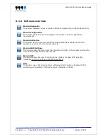
BlueVue Device Manager is a Graphical User Interface for modem configuration and 
administration that allows the user to:

Activate the modem (program the MDN and MIN) for use on the cellular network

Register the modem on the cellular network (WAN Setup)

Configure operation parameters (such as LAN setup or GPS)

Monitor diagnostic and status information

Perform firmware upgrades on the modem

3.1.1   Connecting to the modem

Should you run into any issues connecting to the modem, refer to 

Appendix E: BlueVue Device 

Manager Troubleshooting

.

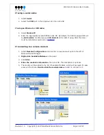
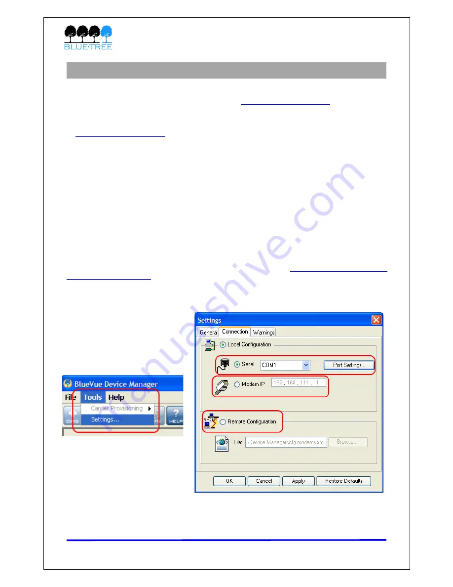
Click on 

Tools > Settings > Connection tab

 to select the interface that will connect your PC 

to the modem.


Figure 6

Revision 1.5

Copyright © 2007 BlueTree Wireless Data Inc.                   Page 17 of 67


Summary of Contents for 4200

Page 1: ...4000 5000 Series User s Guide BlueTree 4000 5000 Series CDMA Modems User s Guide Revision 1 5 Copyright 2007 BlueTree Wireless Data Inc Page 1 of 67 ...

Page 2: ...reless Data Inc All other trademarks are the property of their respective owners Liability Notice While every effort has been made to achieve technical accuracy information in this document is subject to change without notice and does not represent a commitment on the part of BlueTree Wireless Data Inc or any of its subsidies affiliates agents licensors or resellers There are no warranties express...

Page 3: ... harmful interference to radio or television reception which can be determined by turning the equipment off and on the user is encouraged to try to correct the interference by one or more of the following measures Reorient or relocate the receiving antenna Increase the separation between the equipment and receiver Connect the equipment into an outlet on a circuit different from that to which the r...

Page 4: ...4 Activation WAN Setup 20 4 1 Activation 20 4 1 1 Get an account for the modem 20 4 1 2 Program the account information into the modem 20 4 1 3 Confirm the success of activation 21 4 2 WAN Setup 22 4 2 1 Enter the account information 22 4 2 2 Test the connection 23 Section 5 LAN Setup 24 5 1 Ethernet and USB LAN 24 5 1 1 LAN configuration 24 5 1 2 DHCP server 25 5 2 Dial up Networking DUN over ser...

Page 5: ...ripheral using a power relay on the modem s digital output 46 11 8 4 Connecting an analog gauge or source 0 5Vdc to the modem s analog input 47 11 8 5 Connecting an analog gauge or source 4 20mA to the modem s analog input 48 11 9 Mounting the modem 48 Appendix A Firmware Upgrades 49 Appendix B Sending AT Commands 52 Appendix C Basic GPS Reporting in BlueVue Device Manager 54 Appendix D Dial Up Ne...

Page 6: ...g items 1 4000 5000 Series modem 2 15 foot power cable with 1A fuse 3 Extra serial number label 4 5 foot Ethernet CAT5 cross over cable 5 Quick Start Guide also available at www bluetreewireless com 6 Warranty card Table 1 Package Contents Revision 1 5 Copyright 2007 BlueTree Wireless Data Inc Page 6 of 67 ...

Page 7: ...e configured to automatically and autonomously establish a packet data connection to the cellular carrier and acquire a WAN IP address LAN connection this is the local connection between the modem and any device attached to its serial Ethernet USB ports In the case of Ethernet and USB the modem acts as a server and assigns a private LAN IP address to the attached device Alternatively it can perfor...

Page 8: ...and sends raw data to the serial port Remote configuration The user can remotely configure or perform remote diagnostics on the modem using BlueVue Device Manager or a terminal session Remote firmware upgrade The user can remotely upgrade the modem s firmware using BlueVue Device Manager Password protection The modem can be protected from tampering by requesting the user to enter a password before...

Page 9: ...emote server based on an event trigger The analog inputs allow monitoring of gradient data sources The modem s outputs can be used to remotely trigger relays Event Reporting The modem can send a report to up to 10 destinations when a user defined event is triggered The modem has an intuitive embedded Event Reporting Protocol that automatically formats the messages reported to the remote server Tab...

Page 10: ...s downstream and upstream IS95 14Kbps downstream and upstream Programming Setup BlueVue Device Manager software AT commands LED Status Indicators PWR TX RX DTR REG LNK ACT and SER GPS Enclosure Weight Material extruded aluminium Size 166 mm 127 mm 56 mm 6 55 5 00 2 20 Weight 500g 1 1 lbs Cellular Antenna Connection 4200 5200 modems TNC Female Connector 50 Ohms 4600 5600 modems 2x SMA Female Connec...

Page 11: ...0mADC Vce 750mVDC Absolute Maximum VDC 30VDC open circuit Absolute Minimum VDC 0 4VDC open circuit 4x Digital Inputs DI1 DI2 DI3 DI4 Configuration Non isolated level detection reference to ground Active level 1 6VDC to 30VDC Inactive level 0VDC to 1 3VDC Absolute Minimum VDC 0 3VDC Absolute Maximum VDC 33VDC Leakage IDC at 5VDC 150uADC 3x Analog Inputs AI1 AI2 AI3 AI3 only available on 4600 5600 C...

Page 12: ...g or receiving data 169 182 179 188 190 200 Active peak The modem is in a call and is transmitting or receiving data 287 300 300 311 330 340 Idle The modem is either not in a call or is in one but is Dormant The modem is Dormant after 20s of inactivity 49 62 56 67 70 80 Ignition OFF The modem is turned OFF but still has power from its POS input All circuitry is shut down except for Non Volatile me...

Page 13: ...sition Autonomous Operation in Standard Sensitivity Mode Reacquisition 2 sec 90 Hot Start 10 sec 50 13 sec 90 Warm Start 38 sec 50 42 sec 90 Cold Start 50 sec 50 84 sec 90 Cold Start requires no initialization Warm Start implies last position time and almanac are saved by backup power Hot start implies ephemeris also saved Optional COCOM limits Altitude 18 000 m Velocity 515 m s Either limit may b...

Page 14: ...4000 5000 Series User s Guide Table 7 2 4 Modem Views Front Back 5600 Revision 1 5 Copyright 2007 BlueTree Wireless Data Inc Page 14 of 67 Figure 4 ...

Page 15: ...R Data Terminal Ready OFF No terminal is detected over modem serial port ON Terminal host is detected over modem serial port REG Registration OFF Radio is off contact customer support Flashing Radio is registered on cellular network ON Radio not registered on cellular network LNK RF link OFF Not in a data call ON In a data call connected to network ACT RF activity Flashing Transmitting receiving d...

Page 16: ... USB functionality using the RNDIS driver The BlueTree RNDIS driver must be installed before the USB interface can be used You can obtain the driver at www bluetreewireless com 2 6 3 Serial Port DB9 The modem s serial port is an RS232 DCE compliant with EIA 232 standard The connector used is DB9 female and is shown in the illustration below Figure 5 Serial connector looking at back of modem For fu...

Page 17: ...luetreewireless com BlueVue Device Manager is a Graphical User Interface for modem configuration and administration that allows the user to Activate the modem program the MDN and MIN for use on the cellular network Register the modem on the cellular network WAN Setup Configure operation parameters such as LAN setup or GPS Monitor diagnostic and status information Perform firmware upgrades on the m...

Page 18: ...st be installed as explained in section 2 If connecting to a remote modem 1 Select Remote Configuration and click OK A new panel will open to the left of BlueVue Device Manager 2 Right click Available Modems in the panel 3 Click Add 4 Enter the modem s information then click OK The description is optional 5 The modem will be added to the list of Available Modems which will be saved for easy access...

Page 19: ...ivation so that the modem may connect to the cellular network Modem WAN Settings The screen allows the user to set the connection profile on the modem such as the user name and password of the account Modem GPS The screen allows the user to configure the modem for basic GPS reporting Available only for the 5200 and 5600 A modems Help This button opens the BlueVue Device Manager User s Guide a docu...

Page 20: ... Mobile Station ID MIN MSID IMSI the 10 digit or 15 digit number required for Local Number Portability If not provided assume it is the same as the MDN User Name Password Optional required for network access in some cases IMPORTANT Ask your cellular service provider whether the carrier blocks incoming connections If they do you will be unable to communicate with the modem remotely unless you ask t...

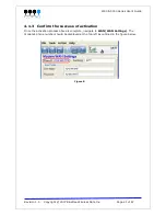
Page 21: ...f activation Once the activation process above is complete navigate to WAN WAN Settings The modem s phone number should be displayed at the top left as outlined in the figure below Revision 1 5 Copyright 2007 BlueTree Wireless Data Inc Page 21 of 67 Figure 8 ...

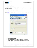
Page 22: ...ormation Navigate to WAN WAN Settings to configure the WAN connection once the modem has been activated Figure 9 1 Enter 777 as the Dial String 2 Enter the User Name and Password if provided by your cellular carrier 3 Select Always On or On Demand explained below depending on the desired connection initiation behavior Revision 1 5 Copyright 2007 BlueTree Wireless Data Inc Page 22 of 67 ...

Page 23: ...ario is when using the serial port in order to establish a PPP session through a Dial Up Networking DUN connection Unless you are sure the modem should be set to On Demand the modem should be set to Always On 4 2 2 Test the connection Once you ve finished entering the settings and once a connection is established depending on the connection initiation behavior described above navigate to DIAG Mode...

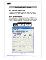
Page 24: ...ether an Ethernet or USB cable is used it is essential that both the modem and the attached device be within the same LAN subnet for IP communication to take place By default the modem has a DHCP server running which will initially assign the following IP address to the attached device providing the device is set to use DHCP Modem IP Host IP Ethernet 192 168 0 1 192 168 0 4 USB 192 168 111 1 192 1...

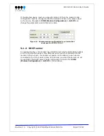
Page 25: ... has a DHCP server which automatically assigns an IP to the attached device If an Ethernet hub or switch is connected to the modem s Ethernet port the modem will assign an IP address to each device connected to the hub or switch Max 254 devices provided the devices are set to use DHCP The DHCP server can be configured or turned off at CONF Modem Configuration LAN IP as shown above Revision 1 5 Cop...

Page 26: ... attached device is not programmable then you cannot do DUN and will have to use the Serial IP feature to communicate with the device Refer to Section 7 Serial IP for details If the modem will be used with a programmable device that can make PPP connections then refer to that device s documentation to create the dial up session The phone number to dial will be 777 If the modem will be used with a ...

Page 27: ...the modem or a host behind the modem however the appropriate port forwarding and LAN IP configuration settings have to be set on the modem Some carriers disable remote access as a security measure If you are certain that the modem is on the cellular network i e it has acquired a WAN IP but you cannot reach it remotely ask the carrier to allow incoming IP data traffic on the required port Read the ...

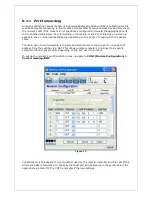
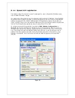
Page 28: ...he port s through which the packet came The main use of port forwarding is to allow an external user to reach a port on a private IP address from the outside via a NAT This allows remote computers to connect to a specific computer within a private LAN depending on the port used to connect To set up the modem s port forwarding rules navigate to CONF Modem Configuration Port Forwarding DMZ The WAN P...

Page 29: ...is local device listens on and just wants everything to work with minimal configuration DMZ can be enabled at CONF Modem Configuration Port Forwarding DMZ 6 1 3 IP Pass through When this feature is enabled the modem will disable NAT and assign its WAN IP address to the attached host The modem will remain reachable though its reserved TCP and UDP ports To enable IP pass through navigate to CONF Mod...

Page 30: ...IP address as well as the modem s ESN in hexadecimal format The IP Registration packet can be sent using either TCP or UDP To configure Dynamic IP Registration navigate to CONF Modem Configuration General and set the destination IP address and port The registration timer is a value in minutes that controls how often the modem should report its IP to the server If it is set to zero the modem will r...

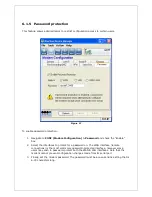
Page 31: ...Enable box 2 Select the interfaces to prompt for a password on The WAN interface remote connections is the most commonly password protected interface however some users may wish to password protect both the WAN LAN interfaces Note that the modem cannot prevent configuration changes made from its serial port 3 Finally set the modem password The password must be a case sensitive string that is 6 30 ...

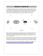
Page 32: ... being passed on to the device This means that the serial device receives raw serial data that it can understand Inversely when the serial device is sending data the modem encapsulates this data in IP packets to be transmitted over the air to the remote destination When a Serial IP server is running the modem waits until a connection is made on the defined Serial IP port then triggers Serial IP mo...

Page 33: ...n the modem can be used to toggle peripheral equipment ON or OFF Peripherals such as lights sirens valves door lock mechanisms and or ignitions can be controlled through these I Os Example of turning ON digital output 2 AT BDOSET DO2 1 Digital Input State Query The modem monitors all of its 4 general purpose digital inputs for a change in state along with the dedicated ignition input The state of ...

Page 34: ...the more complex of the two GPS protocols allowing greater control over the report contents It is configured using a single command string Read Trimble s TAIP documentation to learn to create a command that meets your needs and for report parsing information The document is available here http www bluetreewireless com extranet documents Trimble_ASCII_Interface_Protocol pdf The modem listens on UDP...

Page 35: ...en the modem completely loses power Feature Odometer The modem can keep track of the total distance traveled by aggregating the data obtained from the GPS fixes It calculates the distance traveled based on a straight line between the current and previous fix By appending these calculations to a total the modem is able to keep track of the total distance travelled When using the NMEA protocol the G...

Page 36: ...ample a combination of the timer and speed event triggers could define an event that would trigger when a vehicle has been speeding by defining speeding as moving at 60 mph for more than 10 seconds Reports Once an event occurs the modem sends a report to a set destination All reports with the exception of one unformatted GPS reports are custom formatted by the BlueTree Event Protocol BEP as define...

Page 37: ...expect Cable type Loss per 100 feet 8216 RG58 31 dB 8267 RG213 7 6 dB LMR 400 3 9 dB LMR 500 3 15 dB LMR 600 2 5 dB LMR 1200 1 26 dB Table 10 Installation and verification When installing the antenna follow the FCC and Industry Canada guidelines and keep the following in mind Mount the antenna s at least 30 cm 12 inches from other antennas Do not install the antenna in a closed metallic enclosure ...

Page 38: ...n antenna and the diversity antenna should be 9 The recommended minimum distance between main antenna and the diversity antenna is 18 If it is possible to increase the distance between the two antennas use increments of 9 such as 27 36 45 etc 11 3 GPS antenna The 5200 5600 A modems have an additional SMA connector for the GPS antenna The selected GPS antenna must meet the following specifications ...

Page 39: ...ll need a TypeA TypeB male USB cable You will also need to install the BlueTree USB driver which is available at www bluetreewireless com 11 6 Serial cable The modem has all its serial port pins enabled If all the pins are enabled on the attached serial device it is important to know whether the device is using DTE or DCE as a communication mode The modem is a DCE device so use a straight through ...

Page 40: ...des a 15 foot power cable with 2A in line fuse with on one end a 4 pin Molex MiniFit connector that connects to the modem and stripped wires on the other end to connect to your power source Figure 19 The ignition sense line white wire acts as an ON OFF power switch The modem will turn on when the ignition sense line is set between 8 and 30 volts DC The modem will turn off if the ignition sense lin...

Page 41: ... the modem o The vehicle s Accessory for position 2 for turning ON the modem without turning on the engine o The vehicle s Accessory for position 3 for turning ON the modem only when the engine is turned on Figure 22 11 7 2 Testing the power connection Check the PWR light on the modem if it is turned on then the modem is powered If it s off then review the installation procedures If LED indicators...

Page 42: ... for easy connection to your equipment or sensors Pin Color Label Description 1 BLUE DI3 Digital Input 3 2 ORANGE DI1 Digital Input 1 3 GREEN O1 Digital Output 1 4 BROWN AI3 4600 5600 only Analog Input 3 5 GRAY AI1 Analog Input 1 6 VIOLET DI4 Digital Input 4 7 YELLOW DI2 Digital Input 2 8 RED O2 Digital Output 2 9 BLACK GND GROUND 10 WHITE AI2 Analog Input 2 Table 11 The I O port on the BT 4000 an...

Page 43: ... s digital input Figure 24 1 Connect the negative side of the voltage source to the Ground pin GND 2 Connect the first wire of the panic button or the passive on off sensor to one of the 4 digital inputs 3 Connect the second wire to the positive of a power source 2VDC 30VDC ...

Page 44: ...em s digital input Figure 25 1 Connect the negative side of the voltage source to GND 2 Connect the positive side 0VDC 30VDC of the voltage source to one of the 4 digital inputs 3 Check the polarity of the source before connecting it to the I O connector ...

Page 45: ...y on the modem s digital output Figure 26 1 Connect the positive side of the relay to a positive power source Max 30VDC that corresponds to the specifications of the relay used 2 Connect the negative side of the relay to one of the 3 digital outputs Max current 500mADC ...

Page 46: ...t the positive side of the analog source 0VDC 5VDC to one of the 2 digital inputs 3 These analog inputs are not designed to detect a signal at high speed This approach was adopted to minimize the errors which could be caused by the noise of high frequencies captured by wiring The detection of a DC source with a slow variation will not cause any problems ...

Page 47: ...nput to the modem s analog input ADC 249 and 255 ohms are standard values for a 1 resistor Readings At 20mA the modem reads around 5V on the analog pin At 4mA the modem reads around 1V When the current loop is missing the modem reads 0V 11 9 Mounting the modem The modem requires four 4 screws 3 16 pan or fillister head as well as corresponding lock washers ...

Page 48: ...irmware update procedure then BlueVue Device Manager will not be able to reconnect and finalize the update and the modem will revert back to its previous firmware the next time it is reset If you are able to connect to the modem send the AT command AT BFWUPS 0 to finalize the upgrade and prevent the modem from reverting back on the next reset To learn how to send an AT commands read Appendix B 1 E...

Page 49: ... as this appendix 3 Perform the abt firmware upgrade Figure 30 1 Navigate to CONF Modem Configuration Firmware 2 Click the magnifying glass icon and locate the abt_version upd file from the package that you extracted at step 1 3 Click Upgrade 4 Wait for BlueVue Device Manager to confirm that the firmware update was completed If the upgrade is being performed locally it should approximately take 2 ...

Page 50: ...file you downloaded is identical to the version displayed in the modem information box then the kbt upgrade is not necessary However if the version downloaded is more recent i e it has a higher version number than the version displayed then the kbt firmware must be upgraded The steps to upgrade the kbt are identical to those of the abt file Click the magnifying glass icon and locate the kbt_versio...

Page 51: ... Here is an easy way to do this in Windows 1 Click the Start button then Run 2 In the Run window type command and click OK A command prompt window will open 3 Type telnet xxx xxx xxx xxx 6070 replacing the x s with the modem s IP and press Enter By default the modem s IP will be 192 168 0 1 for Ethernet and 192 168 111 1 for USB If connecting to a remote modem you will need to know its WAN IP 4 Yo...

Page 52: ...mands You will not see what you type until you send the command ATE1 or enable echo in HyperTerminal s settings but the commands will still be sent to the modem Send ATI and confirm that you see the words BlueTree Wireless in the response ...

Page 53: ...matic reports read Section 10 Event Reporting These GPS reports will be unformatted TAIP or NMEA data that can be interpreted by any application written with one of these standards in mind For example the Microsoft s Streets Trips can interpret the modem s GPS output if the modem is using the NMEA protocol To configure GPS reporting navigate to CONF Modem Configuration GPS You will now have to sel...

Page 54: ...e 33 1 Set the reporting timer in seconds This timer is the interval at which the modem will report its GPS position fix 2 Select the NMEA message s to report 3 Click Submit 1b Using the TAIP protocol Read Section 9 GPS Settings for details on TAIP Figure 34 1 Enter the TAIP command that will be used The command shown in Figure 34 acquires and reports its position time and velocity every 10 second...

Page 55: ...ppropriate destination checkboxes For IP destinations select the IP address to report to the port protocol and the port number When done click Submit to save the changes If using NMEA the reports will start coming in immediately although if there is no fix the reports will be empty If using TAIP the reports will not come in until there is a valid fix ...

Page 56: ...iver 1 Click Start Run type control modem cpl and then click OK to open the Phone and Modem Options panel 2 Click the Modems tab and then click Add 3 You may be required to enter location information if this is the first modem installed If this is the case choose your region and area code in the information window 4 Check the box labeled Don t detect my modem and then click Next 5 Select Standard ...

Page 57: ...ue will appear If this is the case select Standard 33600bps Modem and click Next Otherwise proceed to the next step 8 The Connection Name dialogue will appear Type in any name for the connection and click Next 9 The Phone Number To Dial dialogue will appear Enter 777 10 The Internet Account Information box will appear Enter the username and password associated with the account in the corresponding...

Page 58: ...le is required for communication between the modem and the PC A standard Ethernet cable won t do Possible cause 2 The computer s local IP configuration is incorrect Troubleshooting 1 In Windows XP go to Control Panel Network Connections and select the local area connection that corresponds to the Ethernet port in the LAN or High Speed Internet list it s usually Local Area Connection 1 2 Right clic...

Page 59: ...68 0 1 5 Confirm that DHCP is enabled and that the DHCP Start IP is 192 168 0 4 Set the End IP range to any value higher than 192 168 0 4 The default is 192 168 0 39 6 Click Submit to save the changes 7 Reset the modem and restart the computer 2 USB The BlueVue Device Manager message box displays Detecting Modem at 192 168 111 1 indefinitely Possible cause 1 The USB driver is not installed Trouble...

Page 60: ... being used then the DTR LED on the modem will turn on when BlueVue Device Manager attempts to access it Possible cause BlueVue Device Manager is trying to connect to the wrong COM port Troubleshooting Confirm that the correct COM port is selected in BlueVue Device Manager It will attempt to use COM1 by default but computers with built in dial up modems might have COM1 assigned to the built in mod...

Page 61: ...commands Possible cause The modem s firmware and BlueVue Device Manager are incompatible because either or both versions are not current Troubleshooting Upgrade the modem s firmware to the latest version Uninstall BlueVue Device Manager and then install the latest version ...

Page 62: ...s must be configured 1 Verify the signal strength The modem s REG LED should always be flashing when it has a strong enough signal to detect a cellular network Additionally the signal strength is displayed in the information box in the top right of the BlueVue Device Manager window The minimum required for communication is 1 signal strength bar however a signal this weak is not likely to provide a...

Page 63: ...s failing The modem s User Profile will need to be configured Navigate to WAN WAN Settings Enter the user name and password as provided by the cellular service provider 5 Conclusion As mentioned previously when the modem is connected to the cellular network BlueVue Device Manager s Modem Diagnostic screen will display a valid WAN IP and the LNK LED will stay on Figure 39 If after going through all...

Page 64: ...y Local Area Connection 1 2 Right click the connection and click Properties Select Internet Protocol TCP IP in the list and click Properties 3 Write down the existing values in order to restore them if needed then select Obtain an IP address automatically and Obtain DNS server address automatically The computer will now be ready to use the modem to access the Internet Possible cause 2 Serial only ...

Page 65: ...ou cannot communicate with a computer device behind the modem This section is meant for USB Ethernet connectivity If the device is a serial only device skip to the next issue Possible cause 1 Your cellular carrier is operating a firewall which is blocking your attempts to connect Troubleshooting Certain carriers have a firewall turned on by default that blocks all incoming connections 1 Open a com...

Page 66: ...w assumes the modem is configured properly Possible cause 1 The modem and the device are using different serial port settings Troubleshooting Using BlueVue Device Manager navigate to CONF Modem Configuration Serial Port and change the serial port settings to the same values as those of the serial device If the CTS and RTS pins are partially or both disabled set the modem to use no flow control non...

Page 67: ...eTree Wireless Data Inc is not liable for any incidental or consequential damages arising from the use misuse or installation of the BlueTree Wireless modem This warranty does not apply if the serial number label has been removed or if the cellular modem has been subjected to physical abuse improper installation or modification The unit is automatically registered for warranty at the date it is pu...

Reviews: