background image

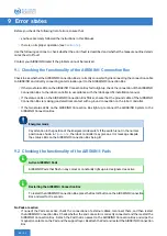
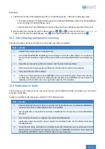
At least one Pad is inactive:

If only some of the Pads are active (but the remaining ones aren’t), check the connections of external cables

and ensure that the active Pad is correctly connected to the nearest inactive Pad. Then restart the AIRSKIN®

Connection Box. Detach the inactive Pad and wipe the magnetic contacts on the Pad and the support layer.

Reattach the Pad and restart the AIRSKIN® Connection Box. Detach the active Pad and wipe the magnetic

contacts on the Pad and the support layer. Reattach the Pad and restart the AIRSKIN® Connection Box.

Check whether the end connector is correctly connected and then restart the AIRSKIN® Connection Box.

All the Pads are active:

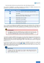
If each Pad is active, the following section shows all the status codes for the individual Pads.

9.3 Status codes of the AIRSKIN® Pads

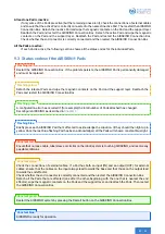
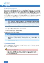
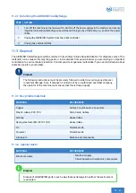
Restart the AIRSKIN® Connection Box. If the problem persists, the AIRSKIN® Pad is permanently damaged

and must be replaced.

Flashing red:

Detach the relevant Pads and wipe the magnetic contacts on the Pad and the support layer. Reattach the

Pads and restart the AIRSKIN® Connection Box.

Flashing yellow:

A configuration error has occurred if (for example) the total number of Pads attached has changed.

Reconfigure AIRSKIN® as described in

Chapter 7

.

Flashing green:

Briefly press each AIRSKIN® Pad that’s affected to acknowledge the situation. It/they should then light up in

yellow. Once the last blue-flashing Pad has been acknowledged, all the Pads will show a constant blue light.

Flashing blue:

Ensure that no loose cable, tube/sleeve or similar on the robot/system is touching AIRSKIN®, and resolve any

possible collisions.

Constant red:

Check the connections of external cables. If a Pad has both an input (IN) and an output (OUT) for external

cables, ensure that the cables on the input always lead towards the base and that those on the output lead

towards the end effector.

Check whether the end connector is correctly connected and then restart the AIRSKIN® Connection Box.

Detach all the Pads that are affected (one after the other, beginning with the one that is nearest the end

effector); wipe the magnetic contacts on the Pads and the support layer, and reattach the Pads. Then restart

the AIRSKIN® Connection Box.

Constant yellow:

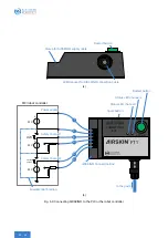
Restart the AIRSKIN® system by pressing the Restart button on the AIRSKIN® Connection Box.

Constant green:

AIRSKIN® is ready for operation.

Constant blue:

49

|

62

Summary of Contents for AIRSKIN

Page 1: ...SAFETYFLANGE OPERATING MANUAL 2020 06 30 v1 2 English Translation...

Page 2: ...Blue Danube Robotics GmbH Donau City Strasse 11 15 A 1220 Vienna Austria 43 1 890 86 97 900 sales bluedanuberobotics com www bluedanuberobotics com...

Page 3: ...2 1 Example 9 3 3 EC type examination 10 3 4 Connection to the safety controller 10 3 5 Components 10 3 5 1 Dimensions of the AIRSKIN Safety ange 10 3 5 2 Flange adapter 10 3 5 3 AIRSKIN Pad 12 3 5 4...

Page 4: ...y instructions for maintenance 51 10 2 Maintenance jobs 52 10 2 1 Cleaning of exterior 52 10 2 2 Detailed inspection with interior cleaning 52 10 3 Jobs following maintenance servicing 55 10 4 Eradica...

Page 5: ...vel e SIL3 The AIRSKIN Safety ange has been developed and manufactured to comply with all the relevant standards and guidelines 1 2 Intended operation The AIRSKIN Safety ange can only be deemed to be...

Page 6: ...3 4 5 1 6 3 8 7 10 3 13 3 16 3 17 17 17 Fig 1 1 Exploded view of the AIRSKIN Safety ange 1When delivered the AIRSKIN Safety ange is precon gured with Spring 2 for 2 5 5 kg payload 2The scope of deliv...

Page 7: ...ern as speci ed by ISO 9409 1 31 5 7 M5 1 AS SF1 TF_31 5 7 M5 14 2 M5x10 cylinder screw DIN 7984 7 2300011 15 2 40 mm Robot ange adapter assembly pattern as speci ed by ISO 9409 1 40 4 M6 1 AS SF1 RF_...

Page 8: ...only transfer the AIRSKIN Safety ange to a third party if it is accompanied by this Manual 2 1 General information about safety 2 1 1 Signal words and warning symbols that are used SYMBOL SIGNAL WORD...

Page 9: ...ot read or understood this Manual in its entirety Clearances AIRSKIN Systems can show clearances Any possible risks that might occur as a result of these clearances must be considered as part of the r...

Page 10: ...must be carried out by specialist personnel 2 2 2 Technical condition of the AIRSKIN Safety ange With the exception of exchanging the optional bias springs the AIRSKIN Safety ange must not be altered...

Page 11: ...signs of damage plastic deformation or other changes In the case of plastic deformation e g due to mechanical wear tear excessive use use in increased temperatures intensive contact with solvents etc...

Page 12: ...e z axis or a displacement around an axis ensues will depend on the type of collision Depending on the nature of the collision the AIRSKIN Safety ange will behave as follows Vertically acting force al...

Page 13: ...ought into service after it has been examined and approved Maximum payload The maximum load for the AIRSKIN Safety ange is 20 kg own weight plus payload and this gure must not be exceeded 3 2 1 Exampl...

Page 14: ...RSKIN are not potential free One must therefore ensure potential equalization between the AIRSKIN Connection Box and the robot controller 3 5 Components The AIRSKIN Safety ange consists of the ange me...

Page 15: ...AIRSKIN Pad Bias spring Cone Tool ange adapter a Robot ange adapter Safety ange cover Plain bearing Sealing gasket b Fig 3 2 Sectional view of the AIRSKIN Safety ange 11 62...

Page 16: ...EDs must always match up If this isn t the case this indicates an incorrect con guration or a fault The Restart button on the AIRSKIN Connection Box is used to safely restart the AIRSKIN system For sa...

Page 17: ...A A A A 135 5 1 63 13 0 5 82 5 89 0 5 Fig 3 3 Dimensions of the AIRSKIN Safety ange in mm 13 62...

Page 18: ...1 31 5 7 M5 Robot ange ISO 9409 1 40 4 M6 9 2 12 2 15 2 11 2 14 2 11 2 7 10 3 13 3 16 3 1 1 1 Tool ange ISO 9409 1 50 4 M6 Tool ange ISO 9409 1 31 5 7 M5 Tool ange ISO 9409 1 40 4 M6 Fig 3 4 AIRSKIN S...

Page 19: ...31 5h7 6 2 8 5 12 4 3 1x45 4 6H7 b 50 mm Robot ange adapter 50 mm Tool ange adapter B B A A B B A A 50 6 2 31 5H7 6 63H8 6H7 R 2 R 2 10 90 4x 6 M x8 9 0 4 x 50 63H8 6 5 10 8 8 M 31 5h7 6 2 8 5 12 4 3...

Page 20: ...2 63H8 6 8 5 10 45 7x M5x8 5H7 b 31 5 mm Robot ange adapter 31 5 mm Tool ange adapter B B A A B B A A 9 3 6 M 2 5 5 2 8 5 11 5 20h7 5 4 4 3 45 7x 31 5 5H7 63H8 20H7 40h8 R2 R 2 63H8 6 8 5 10 45 7x M5x...

Page 21: ...5 10 8 4 3 8 M 4 6H7 8 5 12 25h7 b 40 mm Robot ange adapter 40 mm Tool ange adapter A A B B A A B B M6x8 90 4x 40 10 5 6H7 R 2 R2 25H7 50h8 63H8 8 6 5 9 0 4 x 40 1x45 63H8 6 5 10 8 4 3 8 M 4 6H7 8 5...

Page 22: ...ripper plus the load You can either nd the weight of the gripper on the manufacturer s datasheet or simply use a commercially available set of scales to ascertain this You should likewise ascertain th...

Page 23: ...ng 3 5 7 5 kg payload Once you have ascertained the weight of your particular application you should select the correct spring out of the three springs that are available In order to distinguish betwe...

Page 24: ...ange on a clean surface Please note Watch out for metal shavings or other sharp objects which might damage the AIRSKIN Pad 3 Untighten the countersunk screws 1 and remove the cover 2 of the Safety ang...

Page 25: ...1 2 3 Plain Bearing Washer 1 5 4 6 3 Plain Bearing Washer 2 7 Fig 4 4 Exchanging the spring 21 62...

Page 26: ...rm can substan tially impact on the actuation force that is required The correct con guration of the spring plays a crucial role in ful lling the characteristics described in the following sections se...

Page 27: ...ation force that is required decreases if instead of 5 kg the payload only amounts to 2 5 kg see Figure 5 4 To prevent the characteristics from varying too much there is the option of switching to the...

Page 28: ...is lower ls 200 mm for example at ls 300 mm a payload of 10 kg without spring and a lever arm of lz 50 mm would require an additional actuation force Fxy of approx 6 9 N From the characteristic curve...

Page 29: ...out spring with 10 kg payload Fig 5 3 Required horizontal actuation force Fxy as a function of the vertical distance lz valid for center of gravity ls up to 200 mm 0 20 40 60 80 100 120 140 160 180 20...

Page 30: ...force of 110 N takes effect if with correct spring con guration and maximum payload the collision object is displaced 2 mm against the z axis The actuation force Fz indicated in Figure 5 6 refers to...

Page 31: ...3 with 7 5 kg payload Without spring with 10 kg payload Fig 5 6 Required tilting force Fz as a function of the horizontal distance lxy 0 20 40 60 80 100 120 140 160 180 200 0 20 40 60 80 100 120 Dist...

Page 32: ...around the z axis is coupled with a vertical displacement of 3 mm The actuation forces indicated in Figure 5 10 refer to the necessary static force that as a function of the lever arm lxy the maximum...

Page 33: ...2 5 kg payload Spring 2 with 5 kg payload Spring 3 with 7 5 kg payload Without spring with 10 kg payload Fig 5 10 Actuation force FT required as a function of the horizontal distance lxy 40 60 80 100...

Page 34: ...bot acceleration R The AIRSKIN Safety ange is much more resilient against actuation due to robot acceleration if it is con gured with Spring 1 or Spring 2 with a low payload If one assumes that a payl...

Page 35: ...with 7 5 kg payload Without spring with 10 kg payload Fig 5 13 Robot acceleration R required as a function of the centroidal distance ls 0 50 100 150 200 250 300 350 400 450 500 0 1 2 3 4 5 6 7 8 9 1...

Page 36: ...will already tilt if the robot tilts by 4 see Figure 5 16 In this example minor de ections under 4 that are caused by the robot may indeed be possible yet the AIRSKIN Safety ange is not designed so th...

Page 37: ...th 8 kg payload Without spring with 10 8 kg payload Fig 5 16 Tilt angle required to actuate as a function of the distance from centroid ls 0 40 80 120 160 200 240 280 320 360 400 0 10 20 30 40 50 60 7...

Page 38: ...ion stable surface oor Surface for installation cleaned surfaces of the system robot Air clean frost free as little moisture as possible Temperature 3 C 37 F to 40 C 104 F Adequate room ventilation En...

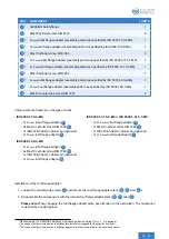
Page 39: ...2 cylinder pin optional 1x 50 mm tool ange adapter 10 ISO 9409 1 31 5 4 M5 or ISO 9409 1 31 5 7 M5 1x 31 5 mm robot ange adapter 12 7x M5x10 cylinder screw DIN 7984 14 1x ISO 2338 5 h8x10 cylinder pin...

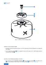
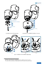
Page 40: ...isaged for this purpose 2 Fix the robot ange adapter 9 that is supplied for the speci c customer to the robot ange by using the corresponding screws 11 Installation of the AIRSKIN Safety ange on the r...

Page 41: ...N Safety ange on the robot 7 10 3 c 8 10 3 d e Fig 6 2 Installation of the AIRSKIN Safety ange 1Component is not included in the scope of delivery 2The scope of delivery includes the robot adapter pla...

Page 42: ...be connected by a quali ed electrician Pay attention to the safety instructions see Chapter 2 6 4 1 Voltage Only connect AIRSKIN to the connections on the robot controller that are indicated in the ro...

Page 43: ...rs on the same AIRSKIN Connection Box can cause the safety cables to remain closed even though one of the two AIRSKIN systems claims an error This operation is prohibited It is possible to supply the...

Page 44: ...safety pulses 24 V safety pulses Equipotential bonding Power supply Safety channel 1 Safety channel 2 CONNECTION BOX 1 2 RESTART FT1 1 2 3 4 5 6 Restart button Status LED channel 2 Status LED channel...

Page 45: ...via LEMO connector d Connection of AIRSKIN pads via JST connector e Operating an AIRSKIN pad on a controller Fig 6 4 AIRSKIN is connected to a controller via the AIRSKIN Connection Box with a supply c...

Page 46: ...cover c Energizer slide switch and 5 5 mm DC jack d External power supply of the AIRSKIN Connection Box via 5 5 mm plug e Energizer slide switch in normal position Fig 6 5 External power supply of the...

Page 47: ...wing any modi cation e g exchange of a part You should check the following items before recon guration Is any cable visible on the outside or hanging loose Is the AIRSKIN Pad mounted rmly and correctl...

Page 48: ...ht up c Flashing status LEDs after releasing the restart button d Release the Spark button on successful recon guration e Restart the system by pressing the Restart button f Actuate blue ashing pads F...

Page 49: ...the controller If the AIRSKIN Connection Box is supplied with 24 V DC by the controller this connection must be checked too If the AIRSKIN Connection Box is supplied with 24 V DC by its own source of...

Page 50: ...he current status of AIRSKIN Use the AIRSKIN Connection Box to recon gure the AIRSKIN System as described in Section 7 2 7 In order to check functionality each AIRSKIN Pad in the system must be presse...

Page 51: ...as prescribed Pay attention to safety instructions AIRSKIN cannot function properly if it is not free of collisions when it is switched on 8 2 Switching on the AIRSKIN System The AIRSKIN System is swi...

Page 52: ...ntact with a ground connection on the robot controller If the two status LEDs on the AIRSKIN Connection Box light up reconnect the AIRSKIN System to the AIRSKIN Connection Box Energizer mode Pay atten...

Page 53: ...x Flashing yellow A con guration error has occurred if for example the total number of Pads attached has changed Recon gure AIRSKIN as described in Chapter 7 Flashing green Brie y press each AIRSKIN P...

Page 54: ...ad is pressed brie y ve times Then the AIRSKIN pad has to be actuated as soon as it lights up purple and released when it goes out Finally the AIRSKIN pad must be pressed brie y three times then the r...

Page 55: ...AIRSKIN is used as an active safety function for the system straightforward maintenance jobs can also be carried out by regular personnel because this presents no danger to them Switching off or bypas...

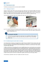
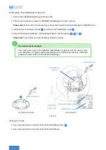
Page 56: ...ested before extensive use 10 2 2 Detailed inspection with interior cleaning This more extensive maintenance work requires the complete removal of all pads from the machine Clean each pad on all sides...

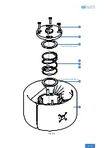
Page 57: ...1 2 3 Plain Bearing Washer 1 5 4 6 3 Plain Bearing Washer 2 7 Fig 10 2 53 62...

Page 58: ...note Ensure that no foreign bodies penetrate the inside Information about lubrication The components used in the AIRSKIN Safety ange are designed for dry running How ever lubrication can improve slid...

Page 59: ...maintenance 5 Carry out a trial run of the machine 6 In the case of maintenance without AIRSKIN as an active safety feature Only remove the bar rier tape and warning notice that clearly identify inact...

Page 60: ...CTION 1 Turn off the machine at the main switch Switch off the power supply to the machine and secure it against unintentional starting up as well as switching on by a third party e g enclose the powe...

Page 61: ...es authorities if you need information about collection points in your locality Disposal The following instructions must be precisely followed in order to avoid any possible envi ronmental damage Even...

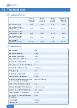
Page 62: ...cal Maximum load 20 kg Maximum acceleration 15 m s2 Maximum actuation force 110 N Displacement z axis rotatory 10 Repeatability z axis rotatory 0 08 Displacement in z direction translatory 3 mm Repeat...

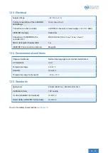
Page 63: ...gth of Supply cable 3 m AIRSKIN Pad connection internal Magnetic 12 4 Environmental conditions Chemical resistance Normal cleaning agents oil alcohol disinfectants UV resistance 100 Temperature range...

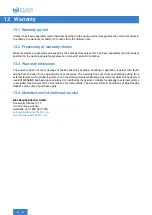
Page 64: ...ling or operation together with faults arising from the use of non original parts or accessories The warranty does not cover any damage arising from external factors such as lightning water re or any...

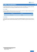
Page 65: ...TTFD mean time to dangerous failure value for the AIRSKIN Safety ange can be derived from the following table PFHD 1 MTTFD 2 DC3 2 5 10 8 2007 57 99 14 2 B10D The stated PFHD value is calculated by as...

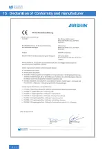
Page 66: ...15 Declaration of Conformity and manufacturer 62 62...

Reviews: