INSTRUCTIONS FOR THE USE OF THE EARTH AUGERS
3.0 ASSEMBLY
Make sure that all parts have been assembled correctly before starting to work.
3.1 Assembly of parts
Handlebar:
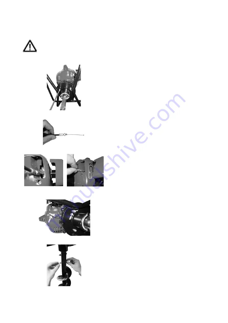
Fasten the engine-reduction unit to the handlebar
using the 3 screws provided (Fig. 2).
Fig. 2
Fig. 3
Fig. 3A
Fig .3B
Fig. 4
Fig. 5
Throttle cable connection:
for easier assembly of the throttle cable, we recommend
removing the air casing from the carburetor filter.
The throttle cable that exits from the accelerator handle has a
threaded terminal at its end, a nut screwed onto the terminal, and
a steel accelerator cable emerging from the terminal (Fig. 3).
Take the throttle cable and insert one end into the carburetor
throttle valve’s rotary pawl. Then position the threaded terminal
in its housing in the cylinder cover and pass the steel cable
beneath the respective seat. (Fig. 3A).
Screw the terminal into the engine cylinder cover and adjust the
nut to eliminate excess play between cable and sheath in order to
permit correct and progressive acceleration (Fig. 3B).
In the NEA TJ53E model the adjustment of the terminal is
fastened by a lock nut.
This terminal is a CE-approved safety measure that serves to
prevent the accidental acceleration of the machine if the cable
ever gets caught during work.
Now connect the ground cable’s eyelet terminal to one of the four
screws that fasten the cylinder cover to the clutch case support
and then connect the female faston connector to the male faston
connector coming from the coil inside the engine (Fig. 4).
Earth auger assembly:
now that the engine unit and the
handlebar have been assembled, insert the shaft that comes out of
the reduction unit into the earth auger’s hole and fasten it in place
using the two screws provided (Fig. 5)
GB - 7


